• This forum is the machine-generated translation of www.cad3d.it/forum1 - the Italian design community. Several terms are not translated correctly.

create mesh( volume) between plane and curved surface

  • Thread starter Thread starter Gallup
  • Start date Start date

Gallup

Guest
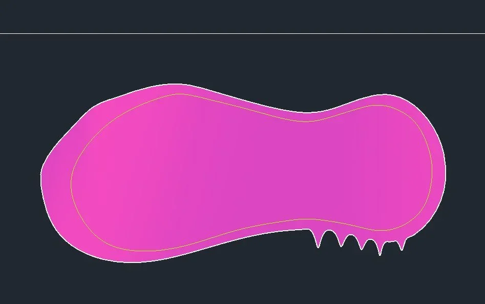
I have a curved surface of an insole, if I open it in abaqus and create a mesh fills it above, then I would have part above flat filled and under remains curve; I want the opposite, I would like to fill in below between the edge of the insole and the lower horizontal plane in the figure, and on leave it as it is, if someone can do it or explain how to do it I would be very grateful, thank you!

Cattura.webp
 
look at the figure, see that under the insole there is a horizontal imaginary plane adjacent to the lowest point of the insole, here I want to have a volume that has as upper part the upper part of the insole (curve surface) and lower the plane that I just said, in other words I want to fill the space between the adjacent lower floor and the insole that as you see has a lower curved part, but I want it flat.
 
with abaqus or geomagic I have no idea how to do it. I'll close the file.

I want to ask you though if someone's behind you at school.

I can also understand the request of the foot, which requires a little experience, since the starting data is a little messed up...but this is stupid, what did they teach you to do with the three-dimensional cad? to revolutionize a sketch?
 
I hope I understand, here it is attached
Yes, the concept is that, but I would like to cut it well, in the sense I don't have to have extra lateral volume, only the lower projection of the basic insole, I explained? because then I have to do simulations on abaqus
 
the file you provided to me is too serrated on the edge, the part that may seem fitting actually is the most extreme part of the starting plantar.

If you need done well, it's the case of surface, not mesh.

If you need a mesh you can always convert.

p.s. I do not know how to use your software
 
In any case, if you tell me how to do it myself without wasting your time
you need to make the plantar a single surface,the base also a single surface,you need to connect with a loft the edges of the two orange and blue surfaces,made wellpiantapiedeImmagine.webp
 
I'll try with my programs, look at how your looks, it seems obvious to me that there is extra side surface, it's not that of your photo projected down, there's lateral volume, I have to remove that by cutting vertically on the edge of the insole, it shouldn't be difficult but I don't know how to do it:dCattura.webp
 
You have to do something like this, I don't want to do it right, :) ,usa sketch 3d,no automatic robberypiantapiede2Immagine.webppiantapiede3Immagine.webp
 
in all cad programs there are commands that allow to project a spline on a surface in such a way that said spline works a cut on that surface. Once the cut is formed, you delete the part that does not interest. there are also commands to extrude the spline to form another surface. in the specific case it is sufficient to extrude the spline (the one that gives the shape to the insole) down to meet a lower horizontal plane.

in the specific case I have prepared a small example. It's done with autocad, but the method and the controls are valid for all modeling programs.
at point 1 you create the spline that will give the shape to the insole. it fills with mesh.
at point 3 there are both mesh and spline. It extrudes the spline down to form the vertical yellow surface, which is cut horizontally helping with a horizontal plane. few steps and the solid is created.
 

Attachments

  • Senza titolo-1.webp
    Senza titolo-1.webp
    65.6 KB · Views: 13
in all cad programs there are commands that allow to project a spline on a surface in such a way that said spline works a cut on that surface. Once the cut is formed, you delete the part that does not interest. there are also commands to extrude the spline to form another surface. in the specific case it is sufficient to extrude the spline (the one that gives the shape to the insole) down to meet a lower horizontal plane.

in the specific case I have prepared a small example. It's done with autocad, but the method and the controls are valid for all modeling programs.
at point 1 you create the spline that will give the shape to the insole. it fills with mesh.
at point 3 there are both mesh and spline. It extrudes the spline down to form the vertical yellow surface, which is cut horizontally helping with a horizontal plane. few steps and the solid is created.
here but we have to deal with a jagged meshplantareImmagine.webpcomunque ecco the thing veilshttps://autode.sk/2oahtp0
 
here but we have to deal with a jagged mesh
I couldn't import the stl file on max.
I would redesign the spline by making it smaller, after which I would project it on that surface to cut the serrated parts. Then I would extrude down that spline to form a solid, and finally I would make a snare using as a cutting object the surface. Finally I would delete the original surface this with autocad. but the same procedure and the same commands are also valid for other programs. In the example, I made it easier.
 

Attachments

  • 1.webp
    1.webp
    19.9 KB · Views: 9
  • 2.webp
    2.webp
    32.5 KB · Views: 9

Forum statistics

Threads
44,997
Messages
339,767
Members
4
Latest member
ibt

Members online

No members online now.
Back
Top