• This forum is the machine-generated translation of www.cad3d.it/forum1 - the Italian design community. Several terms are not translated correctly.

creation mesh with patran

  • Thread starter Thread starter fabius86
  • Start date Start date

fabius86

Guest
hello, everyone. i've been using patran recently. i started importing patterns created in caia and, when i want to create a mesh with hexa8 elements, it tells me that it is not possible as the solid is not triparametric. how can i solve this?
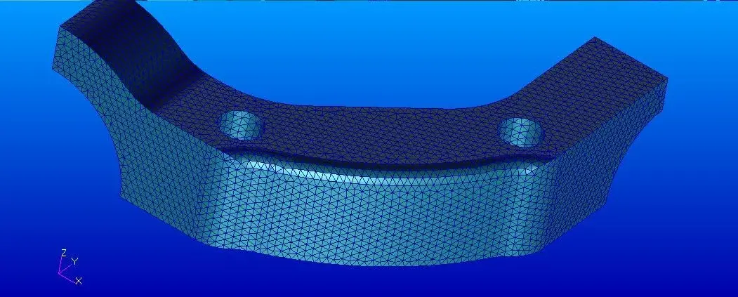
 
I tried with tetraedic elements to 8 knots with mesher tetamesh since the solid is not triparametric, but the mesh is not a great uniform and very satisfying
 
Welcome to Patran.

you can try to make a surface mesh with triangular elements at 3 knots.
then coni various tools added the mesh of superificie (using mesh on mesh for example)
once the surface mesh is in place create volume mesh on the basis of that of surface, using tetrahedral elements to 4 knots.
then transform the tetrahedral elements from 4 knots to 8 knots. 4 knots should not be used possibly.
Be careful that if the surface mesh is not closed perfectly you will not be able to make volume mesh.
 
a mesh is closed if it encloses a volume inside, thus represents a solid.
If you do a free edge check and no edge appears then it's closed. otherwise it's open.
As for your mesh, you have to do a defeature operation of your model before charging it into patran.
in fact patran to make a mesh, put the knots on the edges of the surfaces. it follows that if you have so many rccordo rays, small surfaces, the mesh comes with very small and distorted elements.
You have to decide what's important in the model, and what's not. Before you bring the model to patran, you eliminate everything that is not necessary for analysis. precisely defeature, eliminate useless features.
to make the defeature, if the piece was created in a parametric program, you can make a configuration for the fem. Otherwise you have to simplify it with a cad. then you can meshare or directly solid, or, as I proposed in the previous post, with surface elements, which are easier to change.
 
Thank you very much. Anyway I managed to get a discreetly uniform mesh by making a mesh seed .I set the length of the element to 0.04 and then a mesh tet10 with mesher:tetmesh and with a global edge equal to 0.04.
 
The mesh seems very beautiful.
Do I have any doubts about size? What measuring unit are you working on?
As long as I have no idea about your model, 0.04 is a strange number.
If your model was in meters, it would mean that the mesh side is 40mm. The piece would be huge.
If they were millimeters, it would be a flange of a watch...
I doubt that your piece is in inches, and that your mesh has the side of about 1mm. It would probably mean you drew it in mm and then you didn't realize you imported it in inches.

Anyway, it's a very simple piece, no feature, so mesharlo becomes easy.
 
as usual I forget to set in preference the unit of measurement in mm :). This is an aeronautical component and I exploited the double symmetry for mesharlo. I just started working as a stressist in a company and I'm familiar with patran, but all in all is not very difficult to use.
 
as usual I forget to set in preference the unit of measurement in mm :). This is an aeronautical component and I exploited the double symmetry for mesharlo. I just started working as a stressist in a company and I'm familiar with patran, but all in all is not very difficult to use.
if you import a model in inches, meshi and don't notice, maybe you're still a bit far from knowing how to use :36_6_10:
Besides, mesh alone you do little, you have to apply loads and constraints, and analysis settings, and therefore, of things to learn there are so many. .
 
I know. I have already analysed simple structures to practice and understand how it works. now the next step will be the application of the rbe2 and rbe3
 

Forum statistics

Threads
44,997
Messages
339,767
Members
4
Latest member
ibt

Members online

No members online now.
Back
Top