• This forum is the machine-generated translation of www.cad3d.it/forum1 - the Italian design community. Several terms are not translated correctly.

creation of a belt with different floors

  • Thread starter Thread starter MARCO-90
  • Start date Start date

MARCO-90

Guest
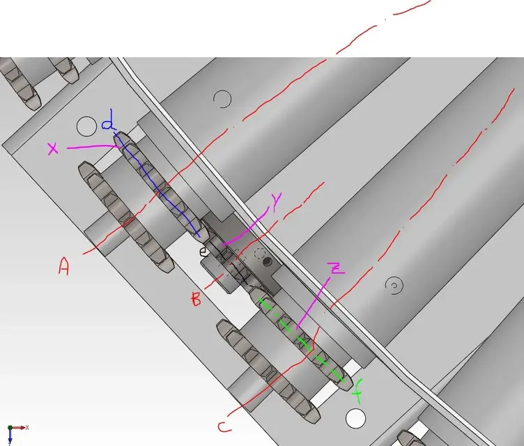
I should create a belt by connecting three pinions.

complication is that a-b-c among them are not aligned.
even d-e-f axes.
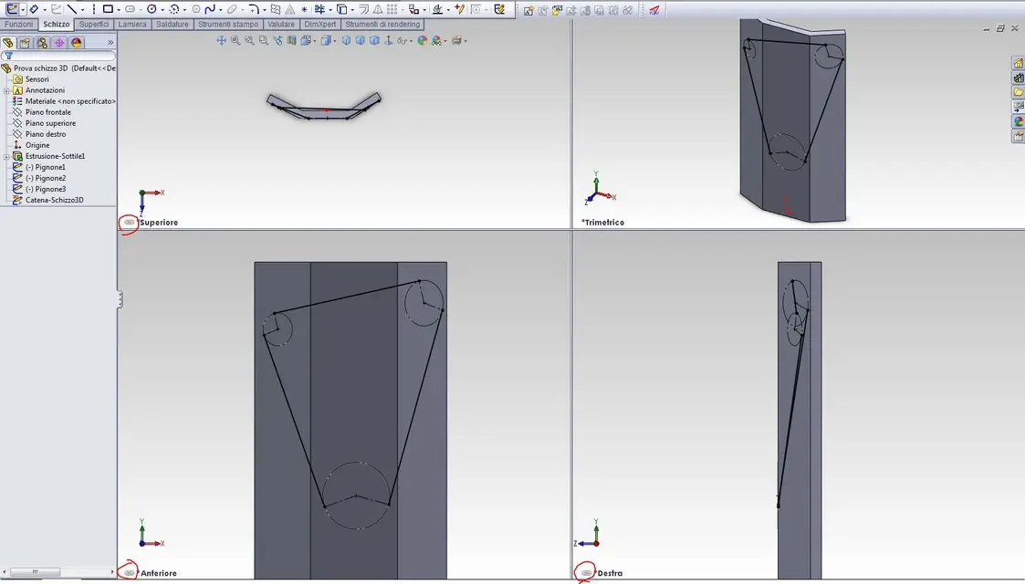
I should build a chain strap around x-y-z axes how can I do it?

I tried with the belt command, but he says it's not possible.
Are there other ways to know development?

I attach photos.
 

Attachments

  • ASSI PIGNONI.webp
    ASSI PIGNONI.webp
    74.8 KB · Views: 29
  • CATENA PIGNONE.webp
    CATENA PIGNONE.webp
    107.3 KB · Views: 25
Last edited by a moderator:
you can probably succeed by creating a 3d sketch and measuring that, out of the belt function.
hi, I was looking at how to solve the problem of the design of the chain and the verification of development with my colleague marco-90 and I suggested to ask him on the forum.

as soon as you have responded we have tried to perform the 3d proof sketch that you find attached: we have seen that tangent coupling does not work in this case and we have solved by building "the old way" the tangences, however, regarding the missing semicircles I did not find solution. . .What was wrong? How can I do that?solved this, we would like to try to draw the chain profile and extrude it following the "chain path". .
ps/ot: when I apply the screen to 4 views, can I "eliminate" the concatenation that causes a view to enlarge the other 2 too? (see attached jpg circle)
 

Attachments

as soon as you have responded we have tried to perform the 3d proof sketch that you find attached: we have seen that tangent coupling does not work in this case and we have solved by building "the old way" the tangences, however, regarding the missing semicircles I did not find solution. . .
And I believe you can't... as you can think that a circle arc can be tangent to a line that is on a plane and at the same time one that lies on a different plane:confused:
With the iron fil you do that circle, but with the compass I see it hard:
you have to use a spline that will make you tangent to the two lines and you will fit to the best to stay, at least in the projected front view, coincident with construction circle.
See Annex
solved this, we would like to try to draw the chain profile and extrude it following the "chain path". .
never used the chain function, tonight I am lazy and do not want to learn:tongue:. to you the honor, I will attach the swx file with the spline you see in the image (you see the "sbile" form of the pseudo circle?) even if you eventually do a sweep and the thing ends there.
ps/ot: when I apply the screen to 4 views, can I "eliminate" the concatenation that causes a view to enlarge the other 2 too? (see attached jpg circle)

right click on the view and... see image attached
 

Attachments

apart from drawing it, how long does a chain last in those conditions?
in fact... is it not better to place the engine with the axis parallel to one of the two reels and think to attack a cardan to the second roller? What do you think?
 
apart from drawing it, how long does a chain last in those conditions?
It's probably a little challenging application that they've been doing for years, and now they'd like to model in 3d. If you think about bicycles with gearbox, they work with heavy breakdowns between pinions.
 
at this point if you want to motorize two rollers and not just one, you should build a small mechanical distributor with two outputs and connect the motor and exit of the cardanic trees
 
It's probably a little challenging application they've been doing for years, and now they want to model in 3d.
That's right! ! !
yes it is a "headed" application for years that is now to be carried in 3d with not few problems between alignments of holes on curves, tilted conical rollers, with shaft axes not aligned with the axes of the holes / sun... pant pant

Obviously the staggering is the one shown by marco-90 in the first attachments and not what I had sketched for a quick simplified test that would be objectively excessive and impractical. . .
the idea of the spline has been successful, we finish the study to show you to me of thanks :d
at this point if you want to motorize two reels and not just one. .
for us it is preferable to motorize the 2 central rollers that in turn will motorize others rather than to start on one side and better align the chains (among other things, it is not if you have noticed that if the gear pin is "vertical", the conical roller pins are also tilted to the vertical of qlc degree to allow the conical roller to work equal from the top).
as I said cmq, the application is that shown by marco-90, with a minimum angle
(for the record, think that some realize roller or tape curves with a single chain ring that "turns" 90°/180° using catene side bow without encountering particular problems - to close you I also add this link al post that speaks of a special chain "3d" that can move freely in the 3 sizes).

thanks again all e.. to the next :d
 
That's right! ! !
yes it is a "headed" application for years that is now to be carried in 3d with not few problems between alignments of holes on curves, tilted conical rollers, with shaft axes not aligned with the axes of the holes / sun... pant pant

Obviously the staggering is the one shown by marco-90 in the first attachments and not what I had sketched for a quick simplified test that would be objectively excessive and impractical. . .
the idea of the spline has been successful, we finish the study to show you to me of thanks :dfor us it is preferable to motorize the 2 central rollers that in turn will motorize others rather than to start on one side and better align the chains (among other things, it is not if you have noticed that if the gear pin is "vertical", the conical roller pins are also tilted to the vertical of qlc degree to allow the conical roller to work equal from the top).
as I said cmq, the application is that shown by marco-90, with a minimum angle
(for the record, think that some realize roller or tape curves with a single chain ring that "turns" 90°/180° using catene side bow without encountering particular problems - to close you I also add this link al post that speaks of a special chain "3d" that can move freely in the 3 sizes).

thanks again all e.. to the next :d
The biplanar chains have existed for several years and serve for example to equip the transport lines of the assembly chains. in any case a biplanar chain does not lend itself to an application like this.
 
The biplanar chains have existed for several years and serve for example to equip the transport lines of the assembly chains. in any case a biplanar chain does not lend itself to an application like this.
no, it is not the classic monorail/birotary/air carrier biplanar/. . .
If you look carefully you will see that it is really special.:finger:
No, of course, there's nothing in our case, but we were talking about chains and strange applications... :wink:
 

Forum statistics

Threads
44,997
Messages
339,767
Members
4
Latest member
ibt

Members online

No members online now.
Back
Top