• This forum is the machine-generated translation of www.cad3d.it/forum1 - the Italian design community. Several terms are not translated correctly.

data tables teething

  • Thread starter Thread starter tinobarbu
  • Start date Start date

tinobarbu

Guest
Bye to all,
I am new to the forum and new in the use of inventor.
I'm going straight to the point, and I'm putting my problem on it. I'm creating models that can be used by my company for the drawings of details.
I have not had many problems in creating a custom cartilage but I have more in setting up "notes" tables; in particular I would need to create a table with gear teething data (which can be conical cylindrical or endless screw), you know if there is a way to extract the data directly from the design module of the same?

I found some sort of solutions to create models with special cartilians for the design of gears, but I don't think I can read the teething data.

Can someone help me with smart solutions?
the ideal would be to have a table created directly by inventor with the data I ask him but I do not know how to do or if you can do it.

another method could be to compile me every time the table, but it will have to be saved model type recallable at the time of need.

thanks to all in advance
 
Hi, Tino.
I'm not an expert, but I think you could create a template in which you'll insert functions (fx) that you could call: module, z, dp, de, øforo etc etc. and to each of these you will impute the value you need.
you create formulas (for example form and z you have to declare them yourself), while dp will function m*z and so on.
at this point the functions can be used to draw the gear. in the table cartilage that you will create you can "rename" these values that will automatically update.
I see if I can get you some screens to explain to me better. .or if someone else has other solutions.
Niche
 
Hello nicola,

Meanwhile thank you for the answer!
In fact I do not need to design the gear, that design it through the appropriate inventor module (in 3d). What I would need is a table where the teeth data designed in 3d are summarized.
at this point the roads I think are two:
1) I create a "template" table that then I fill out the data that I need, in this case, how to create, and where, save, these tables "templates"?
2) Is there a way to extract the data I need directly from the inventor? the question arises spontaneously because the gear was created with the same program and it seems absurd not to be able to extract the data

probably starting the discussion I felt bad
 
I'm sorry I'm late....anywhere I can explain, but besides I'd like someone to explain it because I need it too...
the 3d design that you go to create with the inventor module exploits the parameters you go to insert in the table parameters x case? If we are already at a good point in my view, as it would be enough to extrapolate those values once and update everything, both 3d and tables.
the template you go to save where you already have others, and I think you can already insert a table with a left end the items you need, and to dx the value.
If you create a text field you can (through the insert mask) enter the value of a parameter by clicking on f(x) and choosing it from the list that appears to you. .
in the meantime arrives here and maybe post the file so then we do the rest;-)
 
mm not exactly, the 3d model that I think I do with the gear design module in the "assieme" environment. a mask is displayed in which the input of the teething data is requested, the calculation method, the loads etc., in practice the one explained on this page: https://knowledge.autodesk.com/it/s...60e70d2f-d362-4fce-a8fc-f8759ba2a0af-htm.htmlas described, it is possible to extract the results only in html format.

to today I have set up a table with values that I have to insert manually, it would be cool if these values were related to some generated by the calculation of gears
 
when you create a gear with the design module, it is himself who creates the parameters you enter and he gets from the formulas. then after creating the gear try to enter the part and go on the functions: You should find all the parameters you need, so you can import them to the table.
 
ok the table of the parameters in which the dentatura values are reported I found it, I tried to export it in xml and import it into the drawing but I can not then recall the data in the table.
a method like this but it is not easy if for each gear I have to bring back all the parameters and associate them time by time. extra comfort would be automatic generation.
I'm going to stop and if I find any solution, I'll send it to you.
 
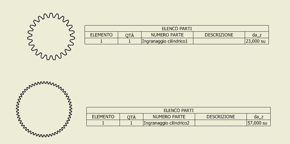
once you find the list you can make a list of custom parts where you insert as columns the parameters you need. when you need those data you just have to choose the list of parts that interest you and select the gear. before you do it, go to the gears and check out the "pass parameters" of those you need so they are seen as custom propertiesParametri.webp
 
Last edited:
I don't understand how it can help me when or want to standardize the table. Perhaps I misunderstood but in doing so I do not have to repeat the procedure for every gear I design?
the same consideration applies to the list of parameters: in the design are not maintained the generated parameters of the model 3d, I have to export them and import them, so at this point I find it more convenient to fill out the table manually.
then tell me if I misunderstood what you are proposing to me,
 
What I proposed to you is to standardize a table parts with only the parameters you need.
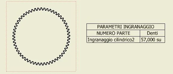
the parameters generated by design are always the same (e.g. da_z). So, yes, since the parameters are always the same, if on each gear the parameters you need you will always have the list parts in place. This is not only true for the number of teeth as in the example I did.Ingranaggio.webp
 

Forum statistics

Threads
44,997
Messages
339,767
Members
4
Latest member
ibt

Members online

No members online now.
Back
Top