• This forum is the machine-generated translation of www.cad3d.it/forum1 - the Italian design community. Several terms are not translated correctly.

delucidation on cocreate versions

  • Thread starter Thread starter crozza
  • Start date Start date

crozza

Guest
hello to everyone is the first time I write here, my name is paolo

in my company, you should start "molating" the 2d of ptc (drawing) to start using the 3d, but we have basic doubts quite important.


I try to ask quite schematic questions, because I always find different answers:

we in company we cocreate modelling 18.1, what difference is there with creo 3.0 and with parametrics 2.0?

as pdm we have model manager, windchill what would it be? What differences? better an external pdm to ptc?

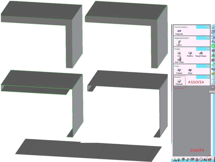
how do you manage the modeling of the sheets? because the basic sheet module (the basic one) looks very sluggish and slow, and above all we give the sheets to be made to thirdists, as factor k what do I put? (We use 1.2, 1.5, 2 and 3 mm)

we build machinery, we are in 4 in the technical office, so it is not huge, do you have advice on how to move?

I hope you don't miss important info.

Thanks for the help.
 
cocreate, a modeling company, a "direct" modeling cad, was purchased from ptc (parametric), which made a cad of opposite philosophy that is purely parametric that in a few words makes you draw the sketch from which the solids are born with the parameterized quotas, then you enter the sketch, change the measure of the quota and you automatically change the bonds that you have associated with all.
Usually direct modeling is more advantageous for those who design and design very varied objects, the parametrised modeling is great for those who build more similar objects like hydraulic cylinders: you set the parameters various alesaggio, stelo, shirt and racing and he automatically redesigns the complete cylinder.

the ptc buying cocreate tried to create a software that allows you to use at best both procedures, for example in cocreate added 3d annotations that are 3d odds that you change you vary the 3d automatically.

regarding the pdm I use that of the cdm isigraf first jclient then pe3 and I must say that I found it remarkably beneficial compared to model manager (it seems to be called so) the original one of the cocreate. Moreover, they can provide you with personalizations that make you easier to codify and save your 3d automatically and finally provide you with commands and macros some of which though seem to be free on the internet and simply translated into English.

As for the plates there is also a sheet module for a fee but I do not know it, I know that from version 18 onwards (I have the 17) they also added the displacement command; I usually use normal 3d modeling and eventually "associated" the material to transform it into sheet metal, in the image there is the example of a 2 mm sheet realizes starting from a parallelepiped and using only:

emptying with distance 30
4 mm fittings, ie the outer connection
emptying with distance 2
move face
associate material and development

Finally a last tip since you are in few you do not put personalizations on the server but leave them local even if it touches you to change them four times, the program automatically every time you close it saves the modifications of the customizations, we who were to the maximum in 3 we had them in technical and has created only scratches
 

Attachments

  • Lamiera.webp
    Lamiera.webp
    53.6 KB · Views: 14
Have you thought well about staying on cocreate? Have you tried other 3d programs? As long as you say... you will find a different comfort with historical modelers....what with cocreate you will not find.

For example, we had come from me10 years, that is, drafting 2d. Well they decided to move to solidworks. as a tool manages files and processes much more traditional, including pdm.

is a bit like windows, linux and apple. depends on what you have to do with it.

I remember that solidworks has the direct modification form, convenient with imported trading parts makes iges or step, or for parts in particular cases. for the rest is parametric.

For example if I have structures a strange hairstyle and bending I have everything parameterized with equations and inserting the base size modifies all the components including the model of the soon finished, that is the cut sheet.
the sheets are managed with all the tools in the field and on can make all the developments you want.
 
Hi.

Thank you for the answers, as a program we will continue to use modelling, given the investment done,

I wanted you to understand the plates as you handle them?

we now draw like a normal piece. while from what I understand you associate to the piece the "how to be a sheet". how do you develop on canned annotations? Of course it gives me a mistake because it finds them all united faces (even after having associated a sheet).

we had thought like in very large tanks to divide it all into details and associate them to a group, but so doing I create a huge amount of work, with annotation etc.

other question, we thicknesses up to 3 mm we develop them with factor k to 0, i.e. the drawing to living edges and take internal-in for the length of the stems and the fold point, (in a few words design without curved edges, I break in faces the design and reconnect them without adding or removing material) but on modelling it is impossible to do, when development calculates the inside line + destination of the radius... .
 
I usually follow reality, ie if the box is formed by 2 folded sheets I make two folded sheets, if they are 4 do 4 etc.
If you make a sheet in which the non-adjacent stems in development touch, he cannot open it, there must be a small margin.
for example of the two boxes in the osd image will be able to develop only the one in which the two sides are a little separated, then to make the development in annotated or you have to select the development board command (that squared in orangen) that will open the 3d vip window with the solids you have in the 3d and you will have to select a face of the solid to develop.
as far as the k factor closest you approach zero and the more development turns out to be the internal boundary of the sheet
 

Attachments

  • Sviluppo.webp
    Sviluppo.webp
    47.7 KB · Views: 9
kaji thank you for your answers,

But when I make boxed with only 4 folds at 90 degrees, I usually develop and pierce it all from the same sheet, so you tell me that if you want to do it on the 3d, I should leave all the shortest edges that do not touch (like 5 tenths) right? But when I make the table in annotation I will see them a double line that doesn't really exist, do I understand?

but when you do a detail that in reality will be composed of two welded plates, I would make 3 codes right? ( 2 sheets and one group of sets of the finished detail).


thanks for the help
If I understand what you want to do, try making a longitudinal cut on your box, as shown in the attached image (which then will be what you do in reality, I guess.
 

Attachments

  • sviluppo.webp
    sviluppo.webp
    103.7 KB · Views: 12
place photos of how I follow now and what I think:

the first photo is how now I design the details
IMMAGINE1.webpThe second picture is how I think you're telling me that I'm done.
Immagine2.webpand gives me the mistake when I try to develop it on the 3d because however the underwoods touch
NOSVILUPPO.webpwhile this is the annotation:
Immagine3.webpthe fact that my finished piece is like the first image, since the lembi balance them, so in the project there should be the "finished" because they secrete all the sheets remain aesthetically different from reality.

then as you can notice in the 2d (as of course it is) remain all the lines, while now in the 2d on drafting we don't have why we draw the finished, and all the changes we make when we produce the development (now the development of the 2d I do them on drafting, I remove the thicknesses and take off the lembi, so the excavations etc I do them according to the tools I have in the workshop (use a punching machine) ).

to develop do I have to round the edges? because when I mix the development to know where I have to bend, it calculates the length flap + half arc of the inner radius, so the measure is "wrong"

I hope I've explained quite well :p

I wanted to know if I'm moving right or not.
 
But when I make boxed with only 4 folds at 90 degrees, I usually develop and pierce it all from the same sheet, so you tell me that if you want to do it on the 3d, I should leave all the shortest edges that do not touch (like 5 tenths) right? But when I make the table in annotation I will see them a double line that doesn't really exist, do I understand?

but when you do a detail that in reality will be composed of two welded plates, I would make 3 codes right? ( 2 sheets and one group of sets of the finished detail).
I am not an expert in sheet metal, usually drawing large pieces, welded and working at machine tools; the plates of 2 mm I use only for the tanks, which classically I do with two c crossed and welded, or for the cophanages.
the "box" sheets usually I have always seen them with the much smaller stems of the central face, moreover I believe that leaving some tenth is a good thing even in reality, because it is better that between the stems there is a little light than a possible interference that leaves you stunned one of the two sheets.

with regard to the placing on the table in the case of the box I make the development and two orthogonal sections listing the stems that appear dissected, where you see the folds, so the double line, as you call it, does not create confusion since a flap is dissected for the other face is visible.

Moreover for the codes I usually make code for each single sheet, code for the particular welded (for example a reservoir) and finally code for the complete axieme ie the complete reservoir of its lid, its filters etc etc etc.

Finally for the bending radius, it should indicate the tip for the fold, and a minimum radius, even 0.1, probably it is necessary to bend the sheet, I classically place a fold radius equal to the thickness and as development I make the inner line for the thin plates, 1/3 inside the mediums, 2/3 the big ones; even if for me the best thing would be to be told by the supplier that rule to follow, so you avoid having to put in place the designs.
 
I am not an expert in sheet metal, usually drawing large pieces, welded and working at machine tools; the plates of 2 mm I use only for the tanks, which classically I do with two c crossed and welded, or for the cophanages.
the "box" sheets usually I have always seen them with the much smaller stems of the central face, moreover I believe that leaving some tenth is a good thing even in reality, because it is better that between the stems there is a little light than a possible interference that leaves you stunned one of the two sheets.
in fact as you see in the image above, I specified that when development etc. I create gaps and holes for the bending that after will be welded and the piece returns as the image 1 (the first I put in the last post).
what I wanted to ask from now on when I design a sheet I already have to think about processing after creating gaps etc, for bending, so that I can create automatic development on annotation?
But so doing in the project there will never be the real finished sheet because I close those excavations with welding. (then the piece returns as the image 1).
But when I see the 3d drawings of the sheets on the internet I never see these developments, how do you work?
with regard to the placing on the table in the case of the box I make the development and two orthogonal sections listing the stems that appear dissected, where you see the folds, so the double line, as you call it, does not create confusion since a flap is dissected for the other face is visible.
I admit I didn't understand what you're saying.Moreover for the codes I usually make code for each single sheet, code for the particular welded (for example a reservoir) and finally code for the complete axieme ie the complete reservoir of its lid, its filters etc etc etc.
it is as we had thought to start working also us to facilitate development etc., because for very articulated tanks I can not know how our supplier will decide to cut it, so I thought to make the pieces with obvious folds and then he will decide to paste the pieces as to cut itFinally for the bending radius, it should indicate the tip for the fold, and a minimum radius, even 0.1, probably it is necessary to bend the sheet, I classically place a fold radius equal to the thickness and as development I make the inner line for the thin plates, 1/3 inside the mediums, 2/3 the big ones; even if for me the best thing would be to be told by the supplier that rule to follow, so you avoid having to put in place the designs.
I have done some tests I have noticed that if I dig only the lembi, and I do not give any angle of fold, leaving alive edge, on the 3d obviously does not fold (which I do not care) while on annotation develops it with factor k to 0 just as I wanted
thanks for the answers in the meantime, you are helping me to understand the concept of how to work sheet metal
 

Forum statistics

Threads
44,997
Messages
339,767
Members
4
Latest member
ibt

Members online

No members online now.
Back
Top