• This forum is the machine-generated translation of www.cad3d.it/forum1 - the Italian design community. Several terms are not translated correctly.

design and develop sheet tub

nikkke

Guest
Hello everyone,
I'm trying to figure out if inventor does it to my case, I've been using it for a few days exclusively in the sheet where I'm slowly making the items I need.

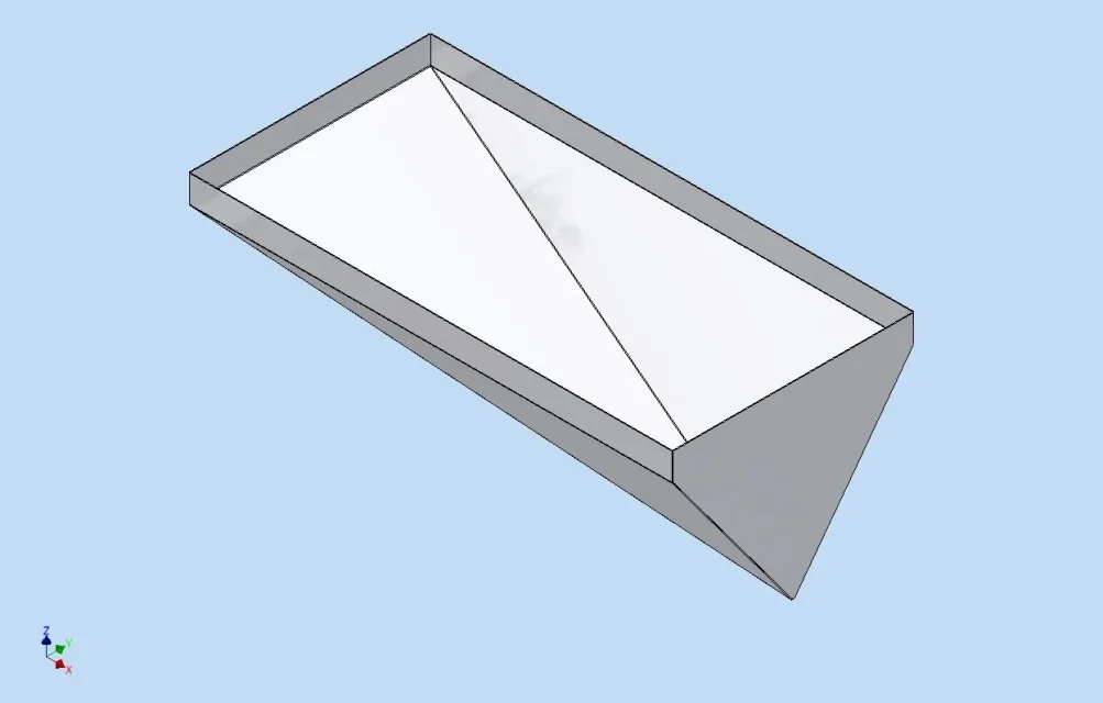
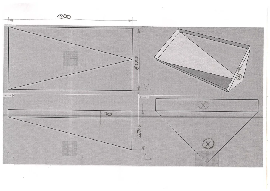
I stopped, however, on the realization of this tub I attach the design. .

to realize it and to develop it with rhino I do not put + of 5 min, but with inventor I have no idea how to do it.

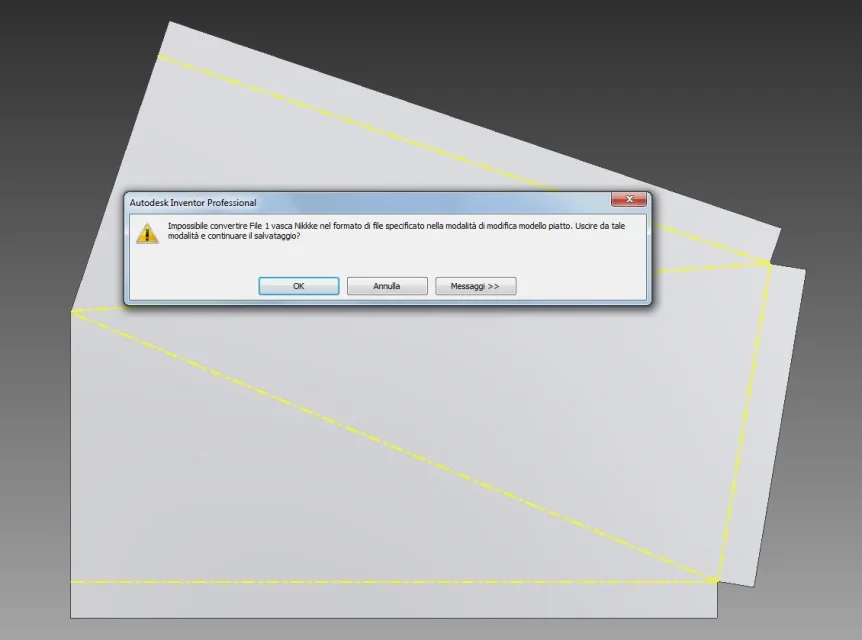
I am looking for the way to manually draw a surface with three inclined points but I do not find the function.. The only one approaching is 3d sketch but then doesn't make me convert it to sheet metal face. .


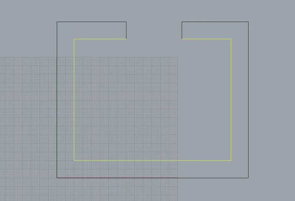
I had done so: sketch 2d and design the face high 470 and wide 600 with the 2 bevels (that with the 2 x.. then offset of the plan of 1200 and design the rectangle wide 600 and high 70.. Then I thought it was possible to create in that way the sloping surfaces with a surface type function for 3 points but I can't find it. .

the only way that made me do this I thought it was to build a passing plan x 3 points using the edges of the surface I want to create, draw the 2d sketch of a side, then create 1 other floor x 3 points, draw another 3d sketch (holding that with the 2d sketch doesn't make me catch the snaps of another 2d sketch so I don't find better way than projecting on the current plane the lines to which I have to connect)
finally convert one at a time the sketches created in the face.. But I don't think that's the system. .


how would you realize it in reasonable time?? I mean no more than 15 min...

thanks x the attention
Hi.
 

Attachments

  • vasca.webp
    vasca.webp
    1.1 MB · Views: 43
  • sviluppo.webp
    sviluppo.webp
    1.4 MB · Views: 42
I use a solid construction system for such a tank and then use the faces as surfaces.
However, I don't know rhino, but if you do the exact developments, and in 5 minutes do everything, keep using rhino.:finger:
p.s. would be interesting if you post the file with the development, so much to give us a look..:biggrin:
Okay as soon as I've got 1 moment I'll put it here with me I don't have any rhino.. Could you explain to me what the procedure you were talking about?
 
Okay as soon as I've got 1 moment I'll put it here with me I don't have any rhino.. Could you explain to me what the procedure you were talking about?
then, parts from sheet environment and create a file that will be your model file and immediately set the thickness you will need to use,
go into modeling environment and use modeling controls to create a solid made as if it were the internal volume of your tub.
from the fittings with radius =thickness where you will make folds to the outside, or fittings with radius = thickness*2 in case of folds to the inside.
then, with the command eliminates face remove the top of the solid, so create your tub with only surfaces.
do another file-lamiera (we key it file 1 ) and derive the pattern file, during the derivation also derives the thickness parameter (which will become thickness1)
- Set sheet thickness with thickness1.
use the "inspection" command and also here sets the sheet thickness with the parameter -choose the faces that will have to be part of the development, and give the ok.
If you have, and it seems to me your case, a total development of multiple parts in sheet metal, do a save by file name 1, change the thickening command by removing the faces you had previously chosen and choose the others you need.
It looks like a long method, but in the time I wrote this post, I can make the developments of your tub.
Not to mention that if I have to change the shape or thickness, I go to do it in the template file, and automatically I also change the remaining developments.
It is not that it adds much, but look at this:http://www.cad3d.it/forum1/showthread.php?32272-modellazione-lamiera-inventor&highlight=sviluppo
 
Thank you 1000 :)
remains only 1 problem: in 3d modeling like I create a solid with that shape without using surfaces? ? ?
I am not used to creating cutting lines to eliminate material.. I usually build everything by putting 1 surface at a time.. made use of rhino
 
here is the tank file developed with rhino.. Let's say that maybe I was too benevolent to say that I put 5 min to do everything with rhino:
I'll put 5 min to draw it and open it.. but then I put on as many x arrange the development as it must, but I made it all in one piece and it is so to my point that I would like to realize it with inventor..

for this I am disappointed so far by inventor's machinability to draw a simple object like this. .
I used for topsolid years that as 3d design concept is very similar to rhino, although rhino x me does not beat it as pure 3d design.. its big defect is not having a sheet development plugin and not negligible the fact of not being parametric. .

returning to the speech inventor I don't think I want to deviate from the sheet metal environment to make this tub. I decided to try inventor x the sheet metal environment, if you want to extract single surfaces I already have other programs I do with before. .

so my question is always the same: how do I make this tub with sheet functions using transmode flanges and so on? ? ?
 

Attachments

with the method described by tarkus you put you and no 3-4 minutes to pull out 3d model, development and quotated board once taken the hand with the commands.

to make a piece like that only with the controls for sheet metal processing I don't think there is a way to get a decent result without losing us eons above, the sheet and solid work in inventor are made to be used on the same piece, it's only a question of a click to change control tab
 
here is the tank file developed with rhino.. Let's say that maybe I was too benevolent to say that I put 5 min to do everything with rhino:
I'll put 5 min to draw it and open it.. but then I put on as many x arrange the development as it must, but I made it all in one piece and it is so to my point that I would like to realize it with inventor..

for this I am disappointed so far by inventor's machinability to draw a simple object like this. .
I used for topsolid years that as 3d design concept is very similar to rhino, although rhino x me does not beat it as pure 3d design.. its big defect is not having a sheet development plugin and not negligible the fact of not being parametric. .

returning to the speech inventor I don't think I want to deviate from the sheet metal environment to make this tub. I decided to try inventor x the sheet metal environment, if you want to extract single surfaces I already have other programs I do with before. .

so my question is always the same: how do I make this tub with sheet functions using transmode flanges and so on? ? ?
Um, uh, he'd say mouse.
I repeat, I do not know rhino, but seeing him some doubt comes to me.
but are you sure it's accurate, taking into account factor k?
I don't see any scars or other typical shapes of the corners, especially where they converge more folds.
to me it seems more the collage of the various faces of your tub, composed on a floor.
Perhaps for thin thicknesses still manages to work, but with thicknesses of 3, 4 mm in my opinion, with a development so already they create errors on the particular bent.
you can post a dwg with the size of the tub and with the indication of thickness, I want to try to make a model with inventor
and compare the development coming out with yours.
so, to try.
p.s.
:36_6_6: I don't know the "hjhkj" program, if you may tell me what version of inventor you use, I can do it with that:36_6_6:
 
Of course, it's exactly as you say, it's a collage of faces.. obtained from an internal offset.. Unfortunately it is 1 great problem of rhino not having a x sheet developer even as plugins..
that development I made to fly x a thickness 2 mm.. folds are considered head against head.. If I wanted to overcome one on the other I would extend the thickness value the fold side I want to keep outside.. changing development in 2d..
These pieces will hardly be made with thicknesses greater than 3 mm.. and x the withdrawal of the sheet is removed from what I know only the value of the thickness up to 3mm..
I'm used to making them always in 2d, helping me with rhino on pieces + challenging, but finishing the development in 2d at the end.. In this case that part I skipped her.. was just x attach 1 development to the flight as an example. .

I said this I wanted to learn a bit to use inventor but I don't know just how to straighten it 1 piece so without building 1 surface x time giving it 3 or 4 points of constraint. .
If you explain to me how to create this figure from 1 solid I would appreciate it.. thanks I have the vers 2015
I don't doubt it, my problem is that I don't know how to get it from a solid. .
 
Okay, as you see, you've got a development that's good for your needs, but it's a bit of a loser."
I see to post as soon as I can the files with the development starting from solid.if we still want to make a comparison, placed all the size of the tub...
 
Okay, as you see, you've got a development that's good for your needs, but it's a bit of a loser."
I see to post as soon as I can the files with the development starting from solid.if we still want to make a comparison, placed all the size of the tub...
the quotas x draw it I would have put them all. .
 
But now I have another doubt about your method:

if I design my internal or external solid I have to consider even if this has alternate folds compared to the design surface,
allego 2 simple examples:
in the first if I make an offset or thickening of the inner profile towards the outside I will get the two upper flanges of the same finite length. .
while in the second example if I make an internal profile offset I have to draw a shorter flange than the other to get both of them 40 once thickened the thickness... also one of the inner faces is shorter than the other. .

Do I also have to take into account this when I design the solid in inventor?? ? ? ?
 

Attachments

  • 1esempio.webp
    1esempio.webp
    16 KB · Views: 17
  • 2esempio.webp
    2esempio.webp
    16 KB · Views: 10
in the case of a profile like that, you... you have to take into account the offset and thickness and bent rays, I was for such a simple profile it is much faster to do it directly in sheet with a face and two flange commands, to decide whether to do it with the solid (or superextrusion) and thickening or from sheet metal depends a bit on the profile type and what changes you will have to do over time.


As far as the tub is concerned, this is how I'd be solid.
sketch and extrusionvasca 1.webp sketch on face and extrusion for removal of materialvasca 2.webpface eliminationvasca 3.webpfor a few weeks I have only the 2009 version of inventor and I absolutely do not remember if the procedure of derivation is always equal or different, in doubt I stop here because I would not create confusion
 
Clear! ! ! ! !
at this point it would only remain to create the division of the edges on the flanges of 70 and to cut in half vertical the face "triangular". so you can open the tub and get a single piece... would this be from the sheet or modeling environment? ?
 
Thank you 1000..

Unfortunately, I'm really prevented with my mother's inventor. .
I wanted to export development to dwg x compare it to my development.. But it doesn't make me. .
I attach the message. .
If I go out of the flat model and carry out it makes me the dwg of the closed model that I don't need. .
 

Attachments

  • errore.webp
    errore.webp
    28.8 KB · Views: 14
here is the screen to superimposed developments. .
yellow is yours.. I would say they match + or -..
I couldn't export the fold lines. .
cmq seems to me to have understood that unless you have to develop very simple things with 90° folds it is better to avoid the sheet environment and go there only x open the molded piece in 3d.. right? ?
thanks to you x the help however:)
 

Attachments

  • sovrapposti.webp
    sovrapposti.webp
    27.2 KB · Views: 10
other thing: then with this method I have to x force draw the inside of the solid then with internal quotas right? ?
because I tried to draw it with external quotas x habit but the edges of the various faces 1 time thickened enter 1 in the other and the faces join.. allego.. there is 1 way then x divide them type surmounted of x weld plates or you have to x force draw the inner thickness? ? ?
 

Attachments

  • spigolo.webp
    spigolo.webp
    14.7 KB · Views: 13
Thank you

Uninstalled inventor!!!! I don't like x anything.. I look for other solutions more suitable for sheet metal parts. .
Anyway, he really disappointed me. .
x I can close the discussion

Thanks again!!!
 

Forum statistics

Threads
44,997
Messages
339,767
Members
4
Latest member
ibt

Members online

No members online now.
Back
Top