@ndreaR
Guest
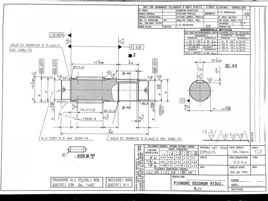
hello to all, I am going to a student of mechanical ing at the athene of bologna. I've been following the forum for a while and finally I've decided to enroll myself taking advantage of the fact that I wanted to ask for your opinions about a mechanical design/design exercise. I would point out that I am a member of the industrial plant curriculum and that these two subjects are not my strong point, but I also understand that they must be part of the cultural baggage of every mechanical engineer. said this I attach you the track of the exercise. the demands were to opt for all commercial components and make changes if necessary, to make a static check of the tree (the latter not I send it for now, to give precedence to another) and then to make the construction design 2d with all the necessary info (quotes, roughness, geometric and dimensional tolerances). I list below the components I choose and my design 2d. If you want to give us an eye and tell me where I was wrong and various other tricks of the trade. Thank you very much!!! :
problem data:
p=13 kw,
No 132 rad/s
number of screw principles = 1
for quotas and commercial components refer to the design and make the appropriate changes.
- bearings
from the type of mounted bearings I hypothesized that the reducer can work in both rows of rotation. for the right bearing I chose from catalog skf a nu 2314 ecp, i.e. a bearing to a crown of cylindrical rollers and in particular the nu type so that it can allow an axial slide (carriage vine). for the right bearings I chose skf 7314 becbp ball obliques arranged with x mounting. These I schematized them as a hinge bond and hypothesized that each of the two takes 50 % of the radial + tangential load and alternately 100 % of the axial one (i.e. the axial load is "absorbed" by a bearing at a time according to the direction of the load). I checked from static load catalog, dynamic with lh10 and maximum number of turns (for the verification of the loads I did not apply the corrective coefficients skf but I obtained directly reactions found solving the isostatic associated with the endless screw. here I ask you how you would have done?). If you need to go further, I will send you the calculations. regarding geometric tolerances I have put total oscillation on seat and shouldering according to skf catalog, but I have not much experience in regurado.
- bearing locking
1) Roller bearing stuck left by ring seeger uni 7435-70 and right by shaft shouldering with check from catalog skf of minimum shouldering radius. I have rectified the seat to ra 0.8 but not the shoulder because it does not work axially (is it correct? )
2) Oblique ball cuscients ( x-mounting) blocked by shouldering (with verification radius min shouldering by skf) and right by a wreath m70 x 2 din 1804 h or alternatively a skf km14 wreath with respective rosette antisvitamento mb14 skf. I then made on the tree the thread for the wreath and the seat for the rosette.
- seals
a left there is a felt seal of diameter 70. I adjusted to 0.8 the seat of the estate (is it necessary even if it is felt? do you need special input bevels?). other question: is it better to replace the felt seal with a oil ?
- tongue
I chose a tab uni 6604-a 20x12x56. having a diameter section 63 mm and a torque moment to transmit about 75 000 nmm I made the choice of length with this formula (which comes from pressure verification) l = (2*mt/(((h-t1)*pamm*d)))+b with
mt = torque; h = tongue height; t1= alt. hollow tree, pamm = 90mpa;d= shaft diameter; b = hollow width;
I found a minimum of 25 mm and chose the l min available for a diameter of 63 mm.
- endless lives
I hypothesized an angle of propeller (delta) of 30° and a pressure (alpha) of 20° I found the forces transmitted as:
t = 2*mt/dp
r = t*tg(alpha)/sin(delta)
a = t/tg(delta)
for the geometric sizes I have made hypotheses starting from the wheel with which I am ingrained and I have obtained form, axial step etc. however they do not evaluate us much on this (we talk more about it if needed). I then put a roughness 0.8 of rectification on the primitive diameter (I have distant memories of technology that rectifies the wheels) while I don't know if geometric controls should be inserted
let me know if you think these choices are correct and if you would have kept that bearing assembly or opted for something different. I also attach the constructive design to you.