Martakynghi
Guest
Hello I seek help in understanding my mistakes I make in drawing.
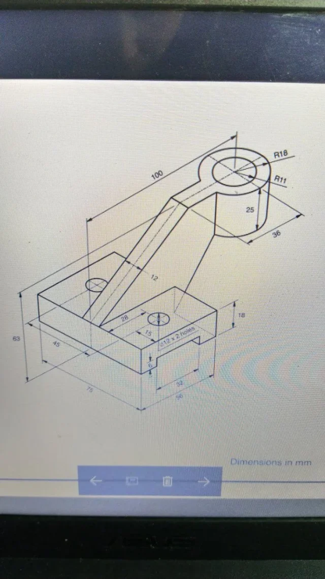
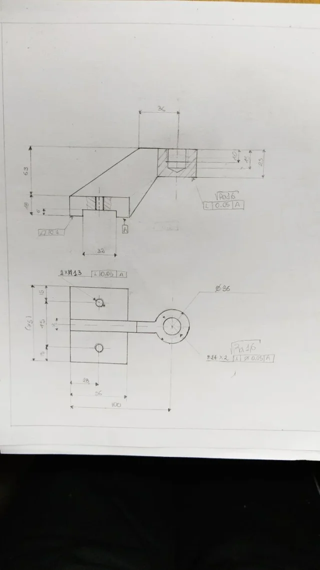
premixed the large hole is considered with a nominal diameter of 12 fine step 2 and is in blind hole instead the small holes are of nominal diameter 13 to large pitch and are passing holes. (exercise given by the professor)
premixed the large hole is considered with a nominal diameter of 12 fine step 2 and is in blind hole instead the small holes are of nominal diameter 13 to large pitch and are passing holes. (exercise given by the professor)