• This forum is the machine-generated translation of www.cad3d.it/forum1 - the Italian design community. Several terms are not translated correctly.

development

  • Thread starter Thread starter Devis
  • Start date Start date

Devis

Guest
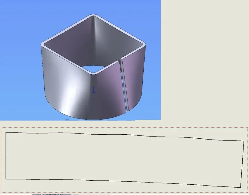
someone can give me a solution to make a cone trunk that has a base of 230 x 366,5 with a height of 327.8 reaching on top a diameter of 198 mm. all in the middle of the axis. if you can show me how to develop it and how it is possible to save it with all the fold lines.
Thank you.
 
If I didn't get it wrong, it's not a cone trunk.
you are trying to make a rectangle fitting 230x366.5 / round ø198 h=327.8 mm

Right?

Hi.
 
Congratulations was what I was looking for, you gave me the solution in very fast times. thanks to the collaboration. Does the Commission intend to take the necessary steps to ensure that the aid is implemented? Thanks again
 
I don't think so.
I used the loft padding function.
Try to see if in the aid you find something for this function.

Hi.
 
Hello, excuse me if I interfere but I wanted to ask pastorman75 how did he build the two sketches?
I mean, how do you know that those degrees and forms are right?
I am doing so xkè type inventor does it automatically, but cm do you know cm draw it from scratch?
 
Hello, excuse me if I interfere but I wanted to ask pastorman75 how did he build the two sketches?
I mean, how do you know that those degrees and forms are right?
I am doing so xkè type inventor does it automatically, but cm do you know cm draw it from scratch?
you need to create two profiles open on two different floors with the same center, you use the sheet loft, defining various data, example how many folds you want.
http://help.solidworks.com/2011/ita.../sldworks/sheet_metal/hidd_sm_lofted_bend.htmexplains how to do it.
 
already cm use the loft function in bending.
the problem is that starting from a circle the program does not find the references cm in the figure of the guide x understand. it is necessary to create the sketch with a polygon cm made pasteurman75. I just wanted to know what criteria you can do something like that.
 
already cm use the loft function in bending.
the problem is that starting from a circle the program does not find the references cm in the figure of the guide x understand. it is necessary to create the sketch with a polygon cm made pasteurman75. I just wanted to know what criteria you can do something like that.
read and look at the pictures.... you have to leave the profiles open at the same point.... make a circle and cut a piece of circumference, make a square under and open a piece of profile parallel to where you cut the circumference, so you have a non-oblique line. .
 
Hello, excuse me if I interfere but I wanted to ask pastorman75 how did he build the two sketches?
I mean, how do you know that those degrees and forms are right?
Yes anes I'm doing this xkè type inventor does it automatically, but cm you know cm draw it from scratch?
Is that a text? :confused:
 
I'll say it again. I can develop it and all that.
but I would need to do it so that all the folding lines cm the image above come out. and with the shizzo of the simple circle does not make them. At least I nn sò cm let them do it. I want to know. is it possible without drawing the polygon instead of the circle?
 
I'll say it again. I can develop it and all that.
but I would need to do it so that all the folding lines cm the image above come out. and with the shizzo of the simple circle does not make them. At least I nn sò cm let them do it. I want to know. is it possible without drawing the polygon instead of the circle?
the bending lines makes you see them at the table anyway, to me in the 2011 version does it also with a circle, with a cut piece, in 2007 I have no idea....
 
the bending lines makes you see them at the table anyway, to me in the 2011 version does it also with a circle, with a cut piece, in 2007 I have no idea....
I figured out what you mean, to read the bending lines he needs to have the same references above and below, if you make a square and make the radius fittings similar to the circle you should do, leaving an open side, automatically get the folds, errors in this process can be 2 or wrong the figure below or above. the function does not wrong and make a square with four ray fittings almost equal to that of the theoretical circle certainly does not cause great changes.
 
Then it must be a limit of 2007 because this comes out to me.
 

Attachments

  • TRAMOGGIA 40x40 H30.webp
    TRAMOGGIA 40x40 H30.webp
    38.9 KB · Views: 9
Last edited:
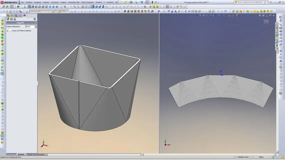
Here are the fold lines.
studies the guide well.
 

Attachments

  • GCS_033.webp
    GCS_033.webp
    127.2 KB · Views: 17
but to do so in this way you didn't start from a round sketch I imagine.
You put straight strokes at where the fold lines start, didn't you?
 
but to do so in this way you didn't start from a round sketch I imagine.
You put straight strokes at where the fold lines start, didn't you?
Yes, as suggested in the guide.
allego screen of a similar hopper
 

Attachments

  • Cattura.webp
    Cattura.webp
    141.9 KB · Views: 22

Forum statistics

Threads
44,997
Messages
339,767
Members
4
Latest member
ibt

Members online

No members online now.
Back
Top