• This forum is the machine-generated translation of www.cad3d.it/forum1 - the Italian design community. Several terms are not translated correctly.

difficulty with loft

  • Thread starter Thread starter Loutenr1
  • Start date Start date

Loutenr1

Guest
Hello, everyone! Maybe I'm losing in a glass of water, but I wondered if it was possible to run with a single loft, the one shown in the photo. the problem is that starting from the circle (plan 1), the loft should end on the planes 2 and 3 tilted each other. Can you? :confused:
 

Attachments

  • loft.webp
    loft.webp
    12.4 KB · Views: 35
Hi.
I don't use sw but I think loft mathematicians are common to all software. so I'd say you can't do it.

you should create a sketch on an inner floor of the piece (plan 4) whose projection on floors 2 and 3 is the basis of what you want to get.
of course the loft penetrates the piece.

I hope I explained.
 
Hi.
I don't use sw but I think loft mathematicians are common to all software. so I'd say you can't do it.

you should create a sketch on an inner floor of the piece (plan 4) whose projection on floors 2 and 3 is the basis of what you want to get.
of course the loft penetrates the piece.

I hope I explained.
I imagined... Okay, for the loft, I solved it like that, advice on how to combine the two sides that come from it? (also here maybe it's a glass of water:tongue:)
 

Attachments

  • loft1.webp
    loft1.webp
    11.5 KB · Views: 15
  • loft2.webp
    loft2.webp
    8.8 KB · Views: 13
I imagined... Okay, for the loft, I solved it like that, advice on how to combine the two sides that come from it? (also here maybe it's a glass of water:tongue:)
with the move face.

Didn't you do an auxiliary plan earlier than inclined arrival and send the loft as you were suggested?
 
I think you have to move the plan inside the piece. ..theoretically by making connections to the "disperate" you can put a piece but everywhere is conceptually wrong.

or at most extend the sloping face (what you call surface 2)
 
with the move face.

Didn't you do an auxiliary plan earlier than inclined arrival and send the loft as you were suggested?
Yes, but I wanted to learn this function too, it is not the first time I find myself in this situation:

but does the "face rash" not have the final bond? I choose the face and the axis on which to rotate it, and can I just tell him how many degrees? Can't I say "until face x"?
 
Yes, but I wanted to learn this function too, it is not the first time I find myself in this situation:
I'm sorry if I insist on you, but I think you should never be in such situations.

Pretend you have to make the piece with a work center. When he sees those geometries, he goes crazy.
 
I'm sorry if I insist on you, but I think you should never be in such situations.

Pretend you have to make the piece with a work center. When he sees those geometries, he goes crazy.
You're partly right. but in this case, the piece is printed, consisting of 2 half. Of course I could have done the sketch of the section so that I didn't have that problem... But then by extruding the section I would have lost what I was trying to do with the loft. I hope you've understood:
 
You're partly right. but in this case, the piece is printed, consisting of 2 half. Of course I could have done the sketch of the section so that I didn't have that problem... But then by extruding the section I would have lost what I was trying to do with the loft. I hope you've understood:
Excuse me, do you have a photo or an image of the finished piece?

look that even if it is printed the problem also arises: how do you make the form (the negative) on the mold?
 
Excuse me, do you have a photo or an image of the finished piece?

look that even if it is printed the problem also arises: how do you make the form (the negative) on the mold?
This is all I can recover, I hope that's enough:)
Of course I thank you for the help you're giving me:wink:
 

Attachments

  • fotocellula1.webp
    fotocellula1.webp
    26.6 KB · Views: 26
  • foto.webp
    foto.webp
    214.2 KB · Views: 29
  • foto (1).webp
    foto (1).webp
    193.7 KB · Views: 17
This is all I can recover, I hope that's enough:)
Of course I thank you for the help you're giving me:wink:
but to do what I see in the photo it is not necessary a loft.
make your beautiful extrusions and then model the thread.
 

Attachments

  • Parte1.webp
    Parte1.webp
    223.3 KB · Views: 16
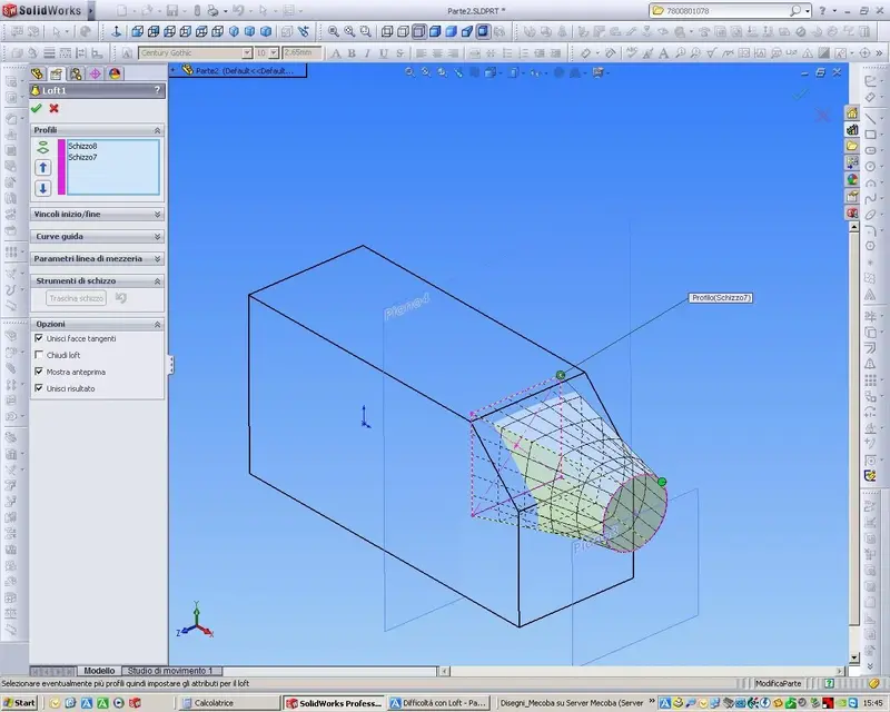
the fact is that the part coming out of the main body, the one to which the connector will be connected, starts from a round section (closer to the connector) and ends in a square section (on the main body), as you see from my drawing in the first message. Of course I could do as mike says, but for laziness and to see if I had been able, I tried with the loft:biggrin:
 
the fact is that the part coming out of the main body, the one to which the connector will be connected, starts from a round section (closer to the connector) and ends in a square section (on the main body), as you see from my drawing in the first message. Of course I could do as mike says, but for laziness and to see if I had been able, I tried with the loft:biggrin:
... and where is the problem... :biggrin:
 

Attachments

  • Parte2.rar
    Parte2.rar
    112.8 KB · Views: 2
  • Parte2.webp
    Parte2.webp
    190.5 KB · Views: 13
If you told me how you joined the parts indicated by the arrow through loft you would do me a pleasure :wink:
 

Attachments

  • Parte2.webp
    Parte2.webp
    193.3 KB · Views: 10
Now I'm in a hurry. If anything, I'll post a little video.
 

Attachments

  • 0.webp
    0.webp
    116.1 KB · Views: 17
  • 1.webp
    1.webp
    94.7 KB · Views: 13
  • 2.webp
    2.webp
    108.5 KB · Views: 11
@luotenr1
Now you know when I said you had to do a vertical plane inside the solid?
Of course I had understood, I wanted to totally review the question as this method is an artifice to achieve the final result. We agree now that the only way to do so is this:cool:.
thanks to all boys (mike screens are enough and advanced, it was very clear also pierarg:finger:)
 
Of course I had understood, I wanted to totally review the question as this method is an artifice to achieve the final result. We agree now that the only way to do so is this:cool:.
thanks to all boys (mike screens are enough and advanced, it was very clear also pierarg:finger:)
Please.

we stay available
 
hello to all

Sorry if I interfere... even if I don't use solidw

hi loutenr1 according to me the ideal solution is the first solution placed by mike, and the simplest and most conventional solution to reach your result, wanting you can use the loft but and one more:biggrin:

Maybe you can try with the sform too? ?

I add some proof with catia so much the concept you have to understand:)

photo 1 method features as mike advice

photo 2 with boolean and multisection loft longer and Moroccan

photo 3 with boolean and multisection loft transfarent before re-elimiting the 2
solids

photo 4 I tried with extrusion cylinder and deform

photo 5 with sfromo you will see a cone

Perhaps you can try with the sform and then wipe with the boolean?? could be a viable solution! ! !

greetings


Attachments

  • metodo feature.webp
    metodo feature.webp
    35.5 KB · Views: 11
  • con booleane e loft multisezione.webp
    con booleane e loft multisezione.webp
    51.2 KB · Views: 21
  • con booleane e loft multisezione trasp.webp
    con booleane e loft multisezione trasp.webp
    53.4 KB · Views: 11
  • ti consiglio anche con sformo.webp
    ti consiglio anche con sformo.webp
    64.3 KB · Views: 10
  • con sformo.webp
    con sformo.webp
    22.3 KB · Views: 9

Forum statistics

Threads
44,997
Messages
339,767
Members
4
Latest member
ibt

Members online

No members online now.
Back
Top