• This forum is the machine-generated translation of www.cad3d.it/forum1 - the Italian design community. Several terms are not translated correctly.

disc joint sizing

  • Thread starter Thread starter danny1204
  • Start date Start date

danny1204

Guest
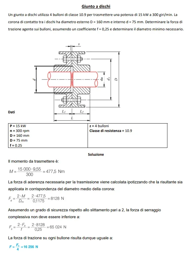
the problem already gives me the data of the joint that is the outer and inner diameter of the resistant crown, gives me the power. use 4 bolts.
I found the torque moment, tangential and axial force of every single bolt. now I have to find the diameter of the bolt (classes 10.9_cioe rel=900n/mm^2).
screws to what size to sigma only (normal or effort gr3 or gr9) (this in case use to rectified stem so they are not subject to cutting)
in the case of cutting I have to use the degree of safety of the screw (manual =1,7-2.5).
I really need someone, if you beat us, I'll also get the problem so it helps me solve it. in mechanics there is no one for repetitions.
 
then: bolts are made to hold a normal effort; so twisting moment agent on the bolt has little meaning.

for your dimensioning do so:
1) you have the power and (imagine) the angle speed of your joint: calculates the torque moment that makes it rotate.
2) You have the inner radius and outer radius of the crown: calculates the average radius (in reality the contact part between the two semi-joints is less, but in the absence of other data, let's settle).
once you have this calculates the corresponding tangential force (ft= mt/r); this force is due to friction between the two joints
3) you have two joints; I guess it's steel against steel. friction coeff f=0.1
calculate the normal force between the two joints. it is fn= ft/f;
4) such a friction force is generated by the 4 bolts that pull. it is therefore
fn/4


At this point you have the bolt class (0the screw-on). know the force that acts along the single bolt and you can calculate the area (and from that in the table you find thread and pitch) of the bolt
 
in your third point when I find fn=ft/f I can increase ft twice (grade of life security? )
if you have time look at my solution and if you vabene
then: bolts are made to hold a normal effort; so twisting moment agent on the bolt has little meaning.

for your dimensioning do so:
1) you have the power and (imagine) the angle speed of your joint: calculates the torque moment that makes it rotate.
2) You have the inner radius and outer radius of the crown: calculates the average radius (in reality the contact part between the two semi-joints is less, but in the absence of other data, let's settle).
once you have this calculates the corresponding tangential force (ft= mt/r); this force is due to friction between the two joints
3) you have two joints; I guess it's steel against steel. friction coeff f=0.1
calculate the normal force between the two joints. it is fn= ft/f;
4) such a friction force is generated by the 4 bolts that pull. it is therefore
fn/4


At this point you have the bolt class (0the screw-on). know the force that acts along the single bolt and you can calculate the area (and from that in the table you find thread and pitch) of the bolt
 

Attachments

  • IMG_20191112_135051.webp
    IMG_20191112_135051.webp
    35.2 KB · Views: 166
  • IMG_20191112_135028.webp
    IMG_20191112_135028.webp
    50.3 KB · Views: 176
Actually, if you are looking on the forum you will find all the formulas for handwritten sizing in different posts.
for example qui
 
Since I have a calculation sheet for joints where the bolt is calculated with old one cnr 10011...I attach results as a result of known torque, minimum diameter and maximum friction band, friction coefficient, number and type of screws.
Screenshot_20191112_230459.webpand then we will get for the screwsScreenshot_20191112_230527.webpto look good, it would be necessary to use uni en 1993-1-8 and above all defines the values for the bolloneria as follows:Screenshot_20191112_231346.webpand therefore, for the traction bolt you will have depending on the precarious system that you need to check:Screenshot_20191112_231619.webpand determine howScreenshot_20191112_231937.webpas you can see occurs screw and joint disk.
 
Last edited:
in your third point when I find fn=ft/f I can increase ft twice (grade of life security? )
if you have time look at my solution and if you vabene
why admissible sigma is worth 300mpa if the screws are 10.9?
What norm did you use?
 
Important note: connections to friction as such do not affect the cut to the screws, otherwise there would not be friction that does not flow relatively the two discs.

Also the choice of multiplication coefficients is questionable because I would expect the screws to verify them according to norm and possibly the pair of the joint would use it with k=2.
 
Last edited:
gunto-a-dischi1-png.32058
as from image, the disc joint follows a proportionally almost standardized, even if you can vary the size.

the traction load of the screws is according to the number of screws, torque and the average diameter of the surface which by friction makes the connection and coefficient of friction.

these concepts are described on all books of mechanics of the superiors.
 
why admissible sigma is worth 300mpa if the screws are 10.9?
What norm did you use?
I used rel (steering load) which would be 900n/mm^2 (10=1000rm - 90% of rm=rel). But then I used gr 3 (in theory it goes from 1.7-2.5 for the lives ) but at least so it is verified to traction and twist (use the formula of von mises in which sigma I can calculate it and the tao I find it from the torque moment applied to a bolt )

is the reasoning right? ?
for the rules I used the manual (if you want I write them later).
on the book of assurance there is no type of explanation you have given (punti).
after I look at them in detail.
 
Important note: connections to friction as such do not affect the cut to the screws, otherwise there would not be friction that does not flow relatively the two discs.

Also the choice of multiplication coefficients is questionable because I would expect the screws to verify them according to norm and possibly the pair of the joint would use it with k=2.
in the sizing I took into account everything, the coefficient you say I put it:
Screenshot (6).webp where 1.1 2 ψ . ÷ is a coefficient that takes into account any dynamic overloads.

cut cut
I don't know if I have to find the cutting force to which the bolt resists or I have to cut it.
I practically use a bolt with rectified stem so it can work to cut and therefore resists to greater torque.


bolts
bolts must be checked at von mises. I have virtually the bullion-resistant area, I have a tangential and axial force (fa=ft*f f= friction coefficient) so I can find the sigma and taoScreenshot (7).webpbut here uses torque moment agent on the bolt obtained from nothing: so I used ft average bolt radius. Is that right? ?
 
Since I have a calculation sheet for joints where the bolt is calculated with old one cnr 10011...I attach results as a result of known torque, minimum diameter and maximum friction band, friction coefficient, number and type of screws.
View attachment 55143and then we will get for the screwsView attachment 55144to look good, it would be necessary to use uni en 1993-1-8 and above all defines the values for the bolloneria as follows:View attachment 55145and therefore, for the traction bolt you will have depending on the precarious system that you need to check:View attachment 55146and determine howView attachment 55147as you can see occurs screw and joint disk.
Points
4-10-11 too complicated I miss the prof will know them.


then another thing since finding the diemtro on which the screws are difficult I used the average contact diameter of the crown, I think it will be a problem since it is great.
 
How confused.

nut: hexagon with threaded hole
screw: male with thread and head
Bolt: I give more lives

what third world book are you using to not have a chapter of bolted links explained?

As a rule as a source, a manual is not enough....you must refer to rules and so much or little are taught....or at least they are marking you on the books.

Oversize randomly and without consistency between the various mechanical elements creates a discompensation and where you don't think the mechanism breaks.

in mechanics normally eligible sigma are given for ductile materials such as rs/1.5 and for fragile materials such as rm/3. for medium dynamic stresses usually you can still make a split 2....but then it is necessary to make verification. sizing alone is not enough.

in the disc joint you will have two contact diameters: one minimum and one maximum. the average diameter is the sum of the divided diameters two. normally the screw diameter is slightly greater to compensate but can be there.
 
a bolted connection affected by cut cut If there are perpendicular forces at the bolt axis. a screw if it has complete thread is less resistant to cutting than a partially threaded if the cutting plane passes into the smooth tract. but don't believe it's so different.Screenshot_20191113_190222.webpif the bolt is not tight enough, the friction force is not generated that contrasts in the opposite direction the force applied to the joint...then in this condition affected by the cut. if the friction does not move the elements of the joint you have not cut.

a bolt affected by traction if subjected to pure traction or bending of the joint. a bolt closed with a certain pair has already traction.Screenshot_20191113_190530.webpthen there are bolted joints that resent mixed traction and cut if they have combined load conditions.

There are many texts, thesis, notes of teachers on the internet to read, understand and study. also if you have good manuals find explanations.

the rules you can find are:
- a cnr 10011 that is no longer in force but is explained practically everywhere and is easily found
- Eurocidice 3 uni en iso 1993-1-8 new concept that is used nowadays since 2005 approximately ahead
- ntc 2008 technical standards Italian state, free of charge, now no longer in force
- ntc 2018 new technical standards of the Italian state, free in force

generic theory is fine, von mises, area, cut, traction etc, but then it is not enough
 
then, just for completeness, besides the bolt to check there is also the plate and in your case the two discs. thinks that the material is not the same as the screws, therefore the pressure of the screws, the tightening and compression, generate a crushing of the material of the disks. the material gets punched....and you need to check.
 
in the sizing I took into account everything, the coefficient you say I put it:
View attachment 55157where 1.1 2 ψ . ÷ is a coefficient that takes into account any dynamic overloads.

cut cut
I don't know if I have to find the cutting force to which the bolt resists or I have to cut it.
I practically use a bolt with rectified stem so it can work to cut and therefore resists to greater torque.


bolts
bolts must be checked at von mises. I have virtually the bullion-resistant area, I have a tangential and axial force (fa=ft*f f= friction coefficient) so I can find the sigma and taoView attachment 55158but here uses torque moment agent on the bolt obtained from nothing: so I used ft average bolt radius. Is that right? ?
attention, that the torque moment of the joint is the couple you have to transmit from one tree to another.

the torque or torque moment of the screw is "how close the screw" that turns into axial force that "holds joints together not to slip".
a screw you can close it to normal 0.7* screw breaker*resistant area.
It doesn't come from nothing.
 
Thank you very much. We usually use gr 3 in the case of fatigue 9.
I was looking at the rules: They are very detailed, they take into account many factors, the problem is that I will not have these norms available only the hoepli manual (incomplete in some parts). we don't have the professor at your level (big problem), think you that the last test I have directly sized the pin to heat since I had already made a mathematical relationship and I already knew it wasn't checked at pressure, he gave me 6. all right calculations perfect all verified, gave me a point in the exercise so much to reach sufficiency.


We come back to us.
one thing I have not clear, when dimensional joint to disk: - the torque moment for the service factor, - when I find the axial force the multiplication for a constant (1,1-2) that takes into account the slip, this only for the axial force not for the tangential force (from which I draw the axial force).

But he asks me to find the cutting force to which he can resist the bolt. he explained to us that if I use a bolt with rectified stem, that is I go to put without game(almost) the bolt can also work to cut so as to resist a greater pair.

Now I have understood the torque majesty of the tree does not hit anything with the bolt, but the moment I have to give to the screw must be such as to guarantee that axial force (as written above : from which I echo the tangential force and from there the torque moment to give to the screw) I think you have understood me. You could tell me the norm from which that formula you wrote, because by doing that I get double the time to give to the bolt.

Thank you, I know I'm breaking you, but I have some small doubts.
 
attention, that the torque moment of the joint is the couple you have to transmit from one tree to another.

the torque or torque moment of the screw is "how close the screw" that turns into axial force that "holds joints together not to slip".
a screw you can close it to normal 0.7* screw breaker*resistant area.
It doesn't come from nothing.
You mean the breaking load or the one with degree of safety.
 
only in case the friction force is not enough go to download the torque moment of the joint as a cutting effect to the screws, because the two joints slip:
t=2•m/(nb•dv)where nb=number bolts, dv=diameter bolts, m= torque motion joint. if they combine all the screws together.

since the partially smooth thread stem results in a nominal diameter you will have a resistant area of:
air=π•d2/4and therefore a tangential tension of the circular section results:
tau=(4/3)•t/ar which must be less or equal to
tau,adm=0.58•rm/gr=sigma,adm•0.58 of the material of the screws.

and so far it is science of generic construction.

if we use uni en 1993-1-8 formulas are slightly different.Screenshot_20191114_031203.webpwhere there are coefficients to norm and not to feeling. . .
Screenshot_20191114_031240.webpScreenshot_20191114_031317.webpScreenshot_20191114_031624.webpOf course they teach worse and worse... and a lot to feeling.
 
We come back to us.
one thing I have not clear, when dimensional joint to disk: - the torque moment for the service factor, - when I find the axial force the multiplication for a constant (1,1-2) that takes into account the slip, this only for the axial force not for the tangential force (from which I draw the axial force).
I only use the service factor or can add a slip coefficient.
 

Forum statistics

Threads
44,997
Messages
339,767
Members
4
Latest member
ibt

Members online

No members online now.
Back
Top