• This forum is the machine-generated translation of www.cad3d.it/forum1 - the Italian design community. Several terms are not translated correctly.

Double cardanic joint

  • Thread starter Thread starter crestus
  • Start date Start date

crestus

Guest
Hello, people!

I write you because I need help!

I am modeling a principle scheme of a double cardanic joint, but I am encountering great difficulties with the study of movement.

I have already searched but I have found nothing but this debate... unfortunately having the 2010 version sp 2.1 I can not see the files :frown:

I said this I tried everything that comes to my mind (cardial joint, reduction of couplings, use of an additional axis instead of the symmetry between the two trees at the extremes, setting a point-by-point movement manually and someone that does not come to mind), but with the study of movement just you do not want to move...(scrowd a little at the beginning, but then it freezes...) on the contrary, turning it turns manually ...

same behavior with a single or simple cardanic. . .


I humbly ask your help... .
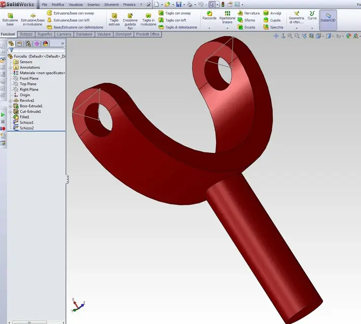
 

Attachments

Hello, people!

I write you because I need help!

I am modeling a principle scheme of a double cardanic joint, but I am encountering great difficulties with the study of movement.

I have already searched but I have found nothing but this debate... unfortunately having the 2010 version sp 2.1 I can not see the files :frown:

I said this I tried everything that comes to my mind (cardial joint, reduction of couplings, use of an additional axis instead of the symmetry between the two trees at the extremes, setting a point-by-point movement manually and someone that does not come to mind), but with the study of movement just you do not want to move...(scrowd a little at the beginning, but then it freezes...) on the contrary, turning it turns manually ...

same behavior with a single or simple cardanic. . .


I humbly ask your help... .
point 1- binding randomly never helps you have a logical follow-up to follow.
point 2- I solved your problem, the main problem is coupling of the active joint in the movement (useless in this case), and angular couplings, and couplings of the axes on the planes, as I have solved, create a cylinder joins it with the external red trees and fix them (one from one side to another), remove the old angular constraints and join the new fixed components with the red trees now and you will see everything go perfectly :finger:
I still play my part though I don't think that with the 2010 version you can open it as I use 2011
 

Attachments

Thank you very much!

Unfortunately no, I can't open the files.. .
The problem is I couldn't figure out much about your description. . :frown:

I'm supposed to go to college this afternoon. Maybe there they have the updated version and I can see them... In case, can I ask you to take a couple of screenshots? At least description of the hand and images under my nose I study what you did. .

just to explain one thing: I didn't randomly match them! (it is true, to do the same mating on one side and on the other I did not use the same system)... they are all derived from different ideas. . are actually 3 different configurations of couplings. . it was necessary to turn off some couplings in order to make the coupling "universal joint" work... :wink:

Thank you again!
 
of nothing however let me know in case I make you some screens, let's say that coupling of the joint was active in the animation, maybe you forgot it, then couple a board on two floors to bind it in the center, it is not the maximum, if you have to create something that goes in the animation you have to try to make pairs as simple as possible, and that you do not contrast between them, in that case it was sufficent to close only the degrees of freedom that they did not serve themselves, trying to close together, trying to not

However in case you let me know that I make you 3 or 4 steps of images with small and short descriptions.
 
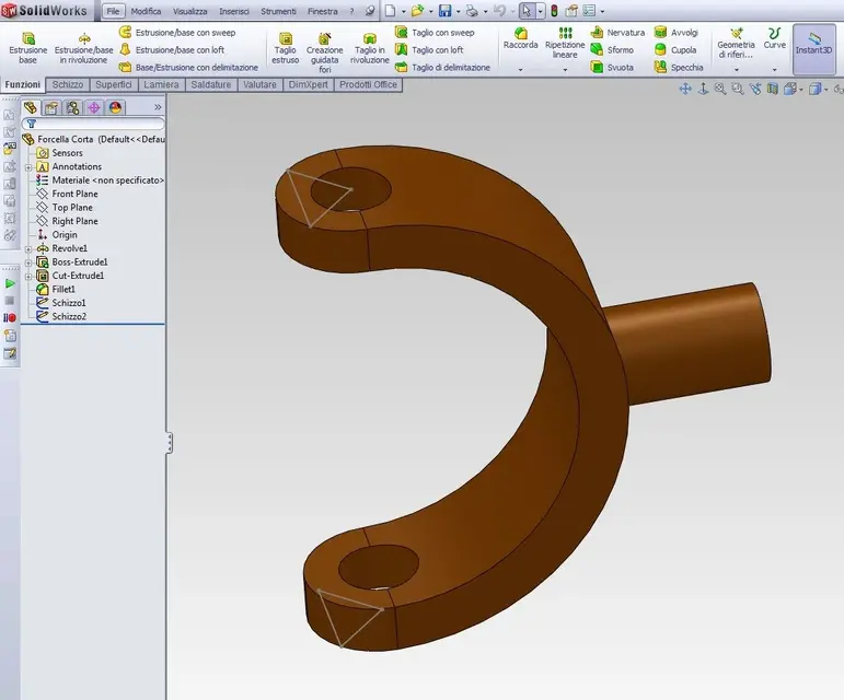
image 1/3 simple triangle (in theory it would only serve 1 point in the center but sld does not read the point as reads the summit).

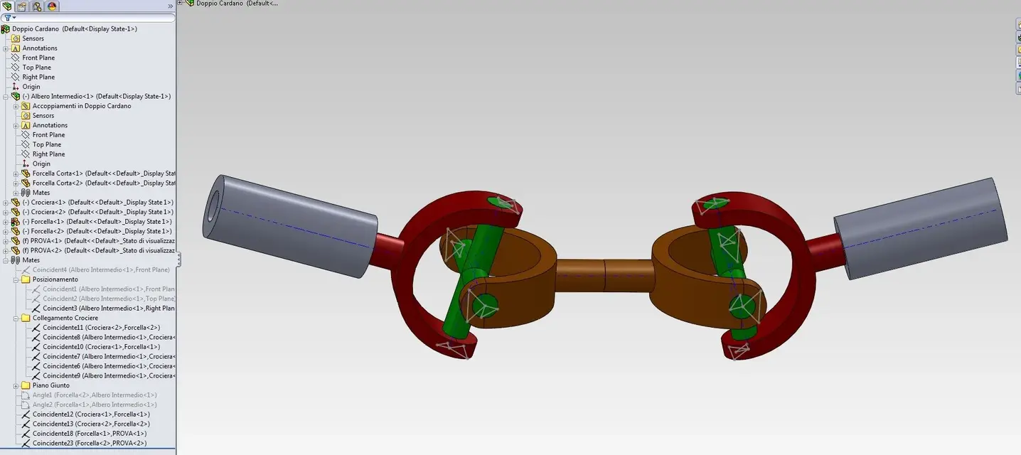
image togetherprv couple the vertices of the triangles corresponding to the centers of the cylinders with the coincidence, green-red and green-gold. pair the matching axes (in place of using the concentric), to be clearer green vertex with red on one side then take axis where you took the green vertex and pair it with hole axis in red, same procedure for gold.

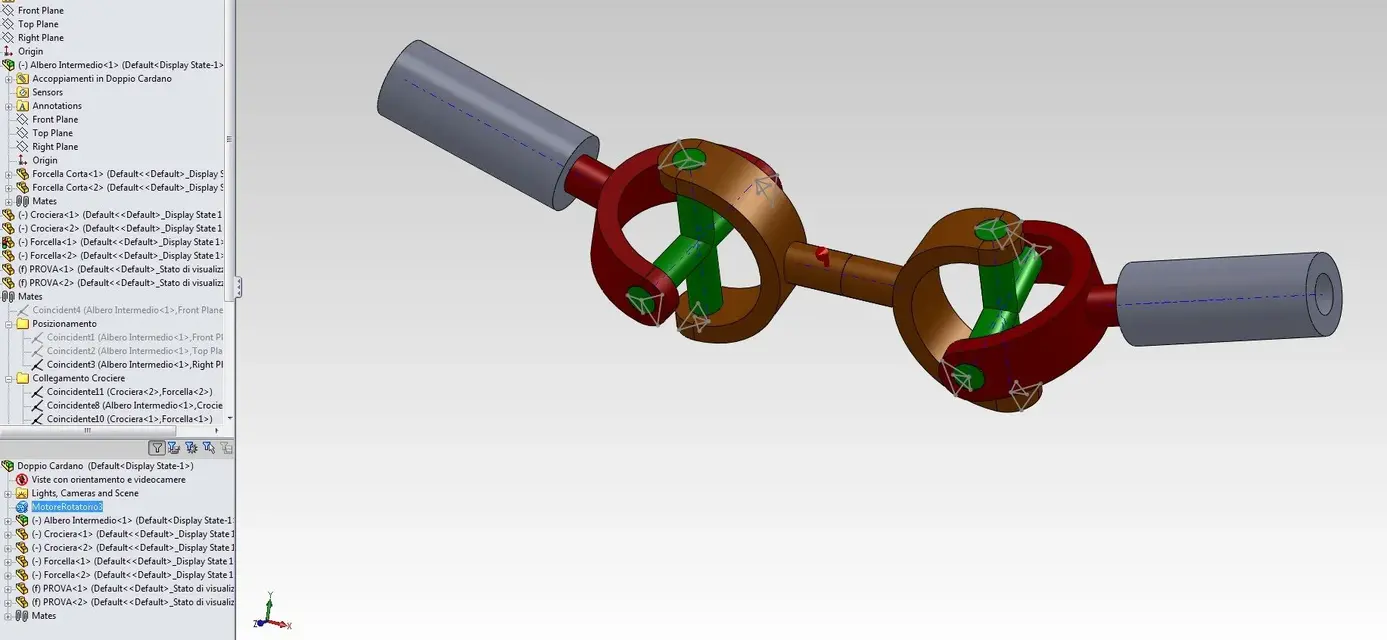
made this activate your constraints by tilting red trees, also let those in the positioning folder. put the two cylinders of "help" couplings axis of the new cylinder with the part of the red cylinder, then set the two cylinders, disable angle couplings and couplings with the intermediate shaft planes

and now go into animation and put an engine on the middle shaft, now it should work perfectly.
 

Attachments

  • 1 triangoli.webp
    1 triangoli.webp
    71.4 KB · Views: 15
  • 2-triangoli.webp
    2-triangoli.webp
    25.9 KB · Views: 12
  • 3 triangoli.webp
    3 triangoli.webp
    65.3 KB · Views: 12
  • assiemePrv.webp
    assiemePrv.webp
    107.9 KB · Views: 15
  • assiemePrv2.webp
    assiemePrv2.webp
    103 KB · Views: 14
I wiped out a couple of pounds of mating.... I don't understand anything.
of movements, but try with this...
Bye.

[youtube]aqknffuyepu[/youtube]
 

Attachments

@crestus, since you don't have the 2011 Realm, watch the video, may be
You can fix it.[youtube]bbnhirskgxs[/youtube]
 
@crestus, since you don't have the 2011 Realm, watch the video, may be
You can fix it.[youtube]bbnhirskgxs[/youtube]
more than anything with these couplings when the movements begin to be more can create problems (eg robot 6 axes, for what in case of movements use axes and I create triangles with sketches to use the vertices) come out more precise couplings that remove only the degrees of useless freedom, in fact the difference is with the concentrics if you take a point to move it (already by hand you see) it moves everything, trammite the axes and vertices only moves.
 
Sorry I didn't answer.... I didn't get to work on it yesterday... but I saw!

I recreated the situation of the first answer ( fortunately the pole has 2011) but I have not yet put myself to "play" with the couplings. . .

Now I'm on what you posted and I'm working! :
 
Sorry I didn't answer.... I didn't get to work on it yesterday... but I saw!

I recreated the situation of the first answer ( fortunately the pole has 2011) but I have not yet put myself to "play" with the couplings. . .

Now I'm on what you posted and I'm working! :
Have fun
 
I finally chose a hybrid way!

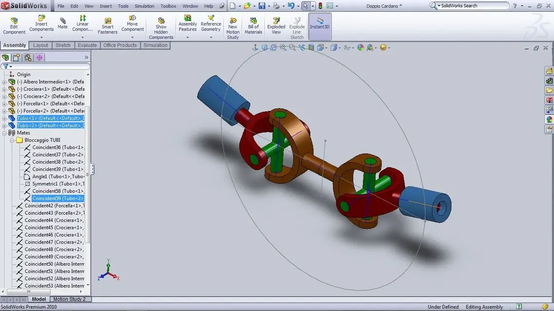
the winning idea was that of the supports! :finger: by mating their centers on a circumference, their axes with two points coincident with the centers of the 2 joints (but not referred to the physical pieces! also these were a sketch aside!), setting the angle between the two axes of the supports and making them symmetrical: This is the result! :tongue:
[youtube]zh8f0_pmeze[/youtube]One screen!
 

Attachments

  • Screen.webp
    Screen.webp
    105.8 KB · Views: 8
Last edited:

Forum statistics

Threads
44,997
Messages
339,767
Members
4
Latest member
ibt

Members online

No members online now.
Back
Top