
• This forum is the machine-generated translation of www.cad3d.it/forum1 - the Italian design community. Several terms are not translated correctly.

draw a mesh of a chain for stranded

  • Thread starter Thread starter ingdottalex
  • Start date Start date

ingdottalex

Guest
Hello everyone,
I have big problems drawing the object in image; is a mesh of a subcarro chain; I am in trouble, I do not know where to begin and how to proceed; It is an object that we do in the company, but my boss does 2d; in the old company there was a designer who only dealt with these pieces and, with thinkdesign they used a week to make a model of this type; Now we have solidworks and I'd be able to draw in 3d, because I think solidworks has all the skills and even in less time! !
so if someone wanted to try; I'd be grateful. also only for advice on how to move me; what to use; a help in short.
Thank you and good luck!


for those who need it I can also send the file to dxf or dwg.
Thank you in advance!
alex
 

Attachments
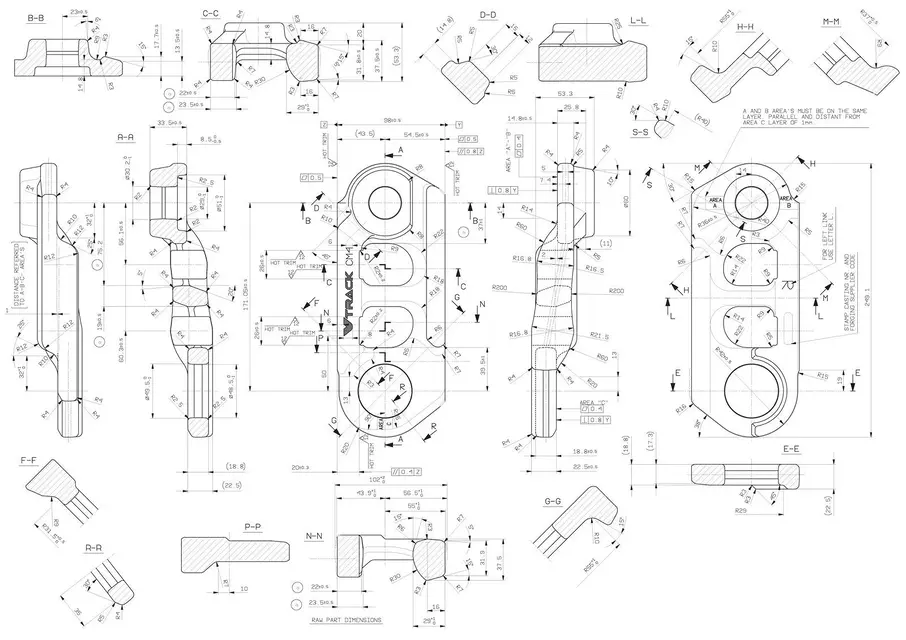
  • magliadicatenasottocarr.webp
    magliadicatenasottocarr.webp
    167.2 KB · Views: 146
Last edited by a moderator:
looking at a slidedge presentation st3, I saw that it is possible to create the 3d by importing the particular table.
Anyway with solidworks, I would import the table dxf and start drawing my shirt step by step.
 
I would also like to draw it step by step, but I don't know where to start and how to move. Would you have any ideas in particular?
 
I, not to know how to read or write I would put myself there (if the time allows, but almost even if it does not allow it) and I would create it just as I had to do it with the cut.
As for 2d to 3d, solidworks also does so, but it is something I would personally avoid like the plague, especially in "delicate" things like this.
 
but this is made of fusion, and in two parts as it divides that line of half-carry. .I don't think you can do just milling; even thinkdesign used surfaces. .
 
the piece has many features but it is not difficult to achieve.
It is about extrusions, cuts and a bit of bevels.
if you do some solidworks internal tutorials, you will easily understand the 3d modeling approach.
I think it takes more time to make the detailed table, than to shape the detail.

If you need someone to do the piece and explain how he did... I think it's a cost-effective operation.
It's hard to find someone who works 2-3 days without getting paid (lose prosacity but, that's how it works).
 
no no indeed; I'd like to learn how to do it. I don't want someone to do it for me; only I don't know, do you think it's possible for thinkdesign to take a week?
 
no no indeed; I'd like to learn how to do it. I don't want someone to do it for me; only I don't know, do you think it's possible for thinkdesign to take a week?
It can be, thinkdesign I used it for 4 years and it's not exactly the program I prefer.
between repeated crashes during the day, constraints to put in sketches (it is a real break at this point of view) ... I think it is much less efficient than other cad.

to start, model the circumscribed parallelepipedo and start cutting the excess parts.
realizes simple sketches, so as to control them with ease and then continue with the reforms, then with bevels and roundings.
try to use the sketch odds consistently, so that you can reuse them even in the table (otherwise it becomes very long).
 
in fact I fully agree with you; thinkdesign abandoned recently; but already the time saved on the creation of models and drawings is remarkable!
 
but do you think it is convenient to proceed cutting and additions?
in general yes.
if a particular is 100 wide, that quota you will use it for drawing.
If you do a 60 wide sketch, and then add another 40 wide sketch, you will get the 60 and 40 odds... and you don't need anything for design purposes and in case of change you have to be careful which of the editing odds.
 
looking at a slidedge presentation st3, I saw that it is possible to create the 3d by importing the particular table.
Anyway with solidworks, I would import the table dxf and start drawing my shirt step by step.
solidworks has been doing it for years.
 
Bye. I currently use solidworks. you have to start from the view that you think it is main, in your case I would start from the one with the vtrack writing, if you are lucky copy paste from the original format in your possession, if not, redesign it. when you copy incolli/drysigns, you will notice that the rows will be blue (in unset format of solidworks=not defined). when the rows are not defined you can move them, and this can give rise to errors. I suggest you define all the writing, adding quotas and reports. You will notice that your lines will pass from blue to black. At this point, when you are finished, "extrude" the piece of the maximum share of your component. Now make the main cuts and holes (the 4 in the center to understand)... to make it always make a sketch on the upper face of the extruded piece, draw the parts to cut and make size (passing or until the next surface). at this point by pressing shift+the left arrow you will notice that the piece rotates 90° clockwise looking at the monitor (of course if you do it with the other arrows rotate in the other directions). Now on the view that you are in front, the side of the piece, "sug" the piece laterally... always draw the sketch with the parts to cut and proceed. That's hard to explain. It's a piece that within 3 hours can be realized both 3d and table. Where are you? If we're lucky and you're not too far away I can make a leap to show you, compatibly with work commitments. I'm in vacation in a few days, so maybe we can combine. always if you go. I don't want to be a teacher to anyone, but now it's a program I've been using for ten years, and if you need advice, I'm happy to give it... Hello, Winner
 
hi vincenzo, in the meantime thank you a thousand of the councils, now I try your way, which as it says maxopus, I proceed for cuts and you info as it goes '; I don't know if we are just neighbors but, we are in modena. Maybe I was wrong starting to get it by rotation extrusions, straight extrusions, sweep..I try with the way of cutting!
thank you and if someone has other advice, always welcome!
 
it could be convenient to use even the disjoining bodies and then join after with a boolean. consider that there is also this possibility.
 
Hello, Alex. would you post the dwg of the piece??? the photo you entered, is not very precise in resolution and there are a couple of measures that you lose when you enlarge.
a question: but this design does not have an isometric view. generally next to sections, detail views etc etc. etc. there is always an isometric view.

:finger:
 
Hi, I put you the dwg, but it's a table made in 2d not modeled, so it would have been difficult to make the isomtrica.
Thank you.
 

Attachments

Last edited by a moderator:
but would someone have time to make the piece? we say at reasonable price or without profit..? :tongue:
 

Forum statistics

Threads
44,997
Messages
339,767
Members
4
Latest member
ibt

Members online

No members online now.
Back
Top