999
Guest
Hello.
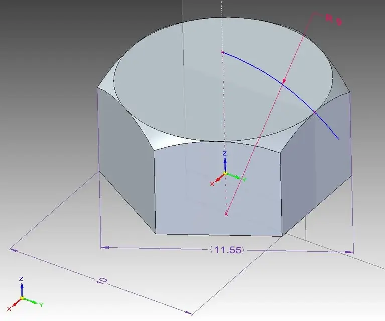
I attend the first year of mechanical engineering, and I have to draw three types of connection (delaying screw, prisoner and bolt) through autocad. There would be nothing difficult, but I have some understanding about the construction of the hexagonal dice and therefore of the head of the screws in the side view. on the text there are some proportions that indicate for example one of the bevel rays like 3/4 and, that is, like 3/4 of the maximum width in the nut, but always comes a very high value. and for the other bevel that values should I use?
Could someone explain to me how to do it or maybe tell me where I'm wrong?
Thank you.
ps: I attach image of the text where the proportions are located.
Attachments

Last edited by a moderator: