• This forum is the machine-generated translation of www.cad3d.it/forum1 - the Italian design community. Several terms are not translated correctly.

dynamic block to iron evenly in two directions

  • Thread starter Thread starter duken
  • Start date Start date

duken

Guest
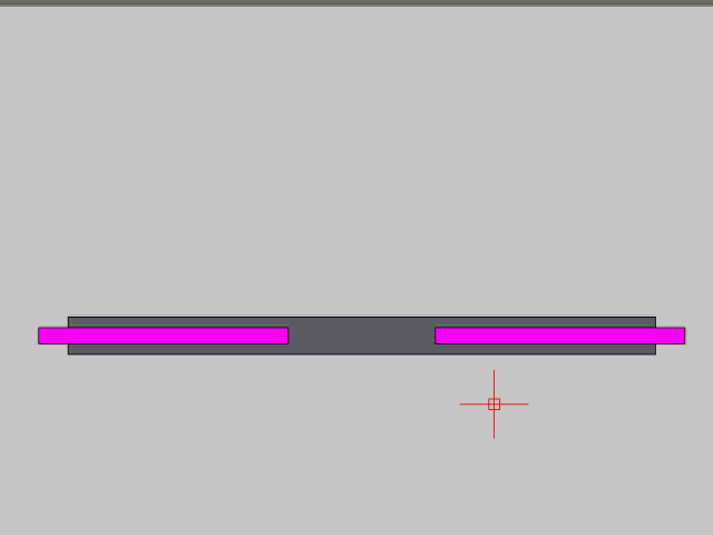
Good evening, I have to make a block that has more attributes,
I explain the movements that should have:
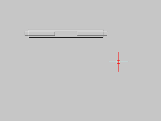
In practice I want to fix the block at the top with the insert point, then below there is a stretching parameter where I press it and drag, all you have to move turning into space.

the problem is that the orange parts must be "opened" with the same extension, so if it has to stretch over the blue part of 200, from both sides should exit 200.

I hope I've been clear. .
I'm trying to try but I can't
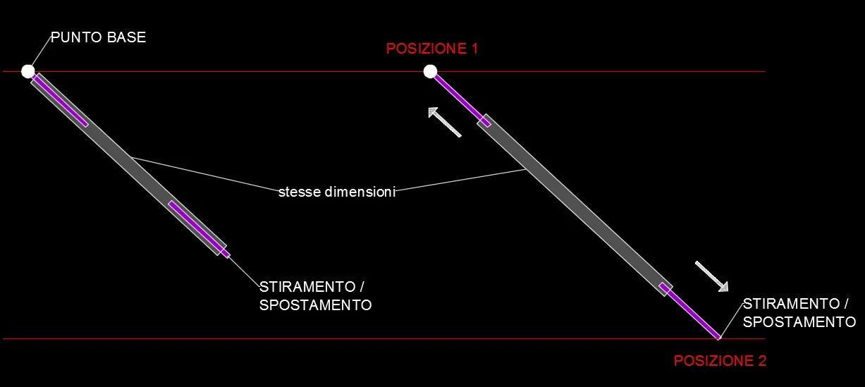
 
it is practically a piombatore, which is used in the formwork to "pipe" the panel.
the central cylinder has fixed dimensions, then with handles you rotate the piombatore that is linked to the exterminities from other two smaller cylinders that have a thread and move on the outside and inside in the same size.
beyond what it is I seem to have explained quite well the movements, in case place another scheme
 
insert a linear parameter to which:
- a moving action to the side cylinder
- a movement action with 0.5 multiplier to the central cylinder

restraints must be associative so that they are in turn ironed.
495.gif
 
Hello, thank you so much.. the fillings really don't need.. you did too much!
I wanted to create the block so that they place it at the point of insertion and then drag it into the desired position, but not in vegetable garden, but with freedom of space. .
then I put a polar parameter on all distance
then I put:
distance type: increase
increase distance: 0
dis min - closed lock length
max : open block length
angle type : increase
angle increment : 0
minimum ang : 0
ang max:360°

But when the drag remains to me the insertion point and the shift in the position before.
Is it not by chance that I should first do the polar stretching and then the procedure you illustrated?
 
Okay.

insert a polar parameter to which to apply:
- polar stretching action to the side cylinder (*)
- polar stretching action with multiplier 0.5 to the central cylinder (*)
- polar stretching action with 0.0 multiplier to the cylinder "pin" (*)

(*) the object selection request, in addition to the cylinder, also select the parameter
 
but what you wrote me in the last post, do I have to do it after I applied the parameters of the video?
or just apply the polar parameter?
is it too much for you to make the process video? (maybe showing also the properties of the value group)

I do not find myself with the selection of cylinders..if I have to select only the end, or the entire aerial of the cylinder
 
Please:

if at the polar parameter assigns minimum and maximum distance, the side cylinders will flow without entering completely or exiting the central one.
496.gif
 
I have another question.. .
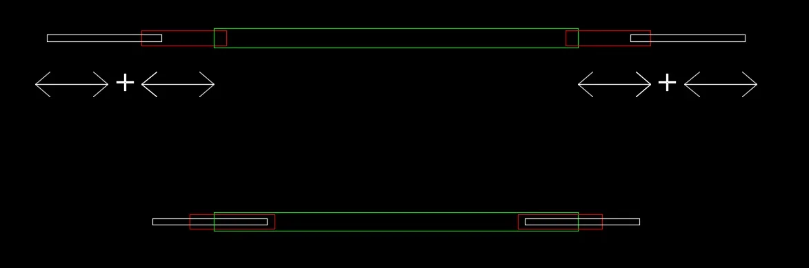
if instead the stems became 2+2 i.e. from the central main cylinder, exit 2 stems, which in turn close to each other..(as in figure, design above all open, under all closed)


Is it possible for you?
Should I make 2 polar parameters instead of 1?
cattura.webp
 
Last edited by a moderator:
you mean a telescopic cylinder......... :
Be sure to see if for gp it is feasible, let us reiterate to its supreme opinion :4410:
 
the process is the same, changes only the multiplier of the distance of each polar stretch applied to the single cylinder.
in order will become: 0 - 0.25 - 0.50 - 0.75 - 1
 

Forum statistics

Threads
44,997
Messages
339,767
Members
4
Latest member
ibt

Members online

No members online now.
Back
Top