• This forum is the machine-generated translation of www.cad3d.it/forum1 - the Italian design community. Several terms are not translated correctly.

excavated sections

  • Thread starter Thread starter makeng
  • Start date Start date

makeng

Guest
Good morning, everyone.
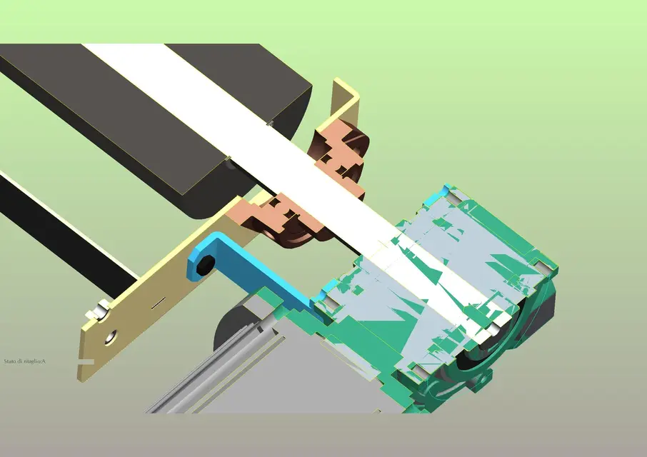
by peeing someone else who used proes (wf5), I realized that when applying sections 3d, the objects interested in the section were "scared". as when applying the command that "dig a volume while maintaining a chosen thickness. is very comfortable especially to understand what happens "back" to the full section.
I tried in every way to find it inside the config.pro but there was no direction. Can anyone help me?
Thank you.
Mar
 
Maybe they were dug because it was surfaces. if they are solid you see the section plan.
Bye.
 
No. I assure you that they were all solid, also because they were mechanical modelling of plant and not design. I took a picture of the axieme as it comes.
 

Attachments

  • cilindro-motore-scarico.webp
    cilindro-motore-scarico.webp
    170.3 KB · Views: 38
I think you're right, prof., the surfaces aren't just used for design.
If you make a revolution or extrusion you can choose to make it solid or surface.
from the image you posted, the solid components and those of surfaces are distinguished.
If that's what you're saying, they'd all be dissected the same way.
 
or are surfaces or solids that pro-e fails to dissect for a precision problem or because there are imported models with little accurate matamics.
It is not a normal function of pro-e.
that type of section you get it with product view which is a ptc viewer.
Bye.
 
As the thing is very comfortable to design, I allowed me to send the subaxieme and to recall the section. as you can see to me it looks solid. bearing support among other things is a step file, so intrinsically solid algorithm....according to me is a configuration command. I'm trying to find out more...
Thank you
Mar
 

Attachments

  • cilindro-motore-scarico-2.webp
    cilindro-motore-scarico-2.webp
    140.9 KB · Views: 20
As the thing is very comfortable to design, I allowed me to send the subaxieme and to recall the section. as you can see to me it looks solid. bearing support among other things is a step file, so intrinsically solid algorithm....according to me is a configuration command. I'm trying to find out more...
Thank you
Mar
the fact that it is a step does not guarantee that the detail is present solid when it is dissected. often I happen to have "empty" sections on details imported from step, it is the usual problem of "open" volumes.
I have never tried but, as they say, it seems that the problem is solved by increasing precision.
 
As the thing is very comfortable to design, I allowed me to send the subaxieme and to recall the section. as you can see to me it looks solid. bearing support among other things is a step file, so intrinsically solid algorithm....according to me is a configuration command. I'm trying to find out more...
Thank you
Mar
I think the matter is different, but try, maybe we find something we don't know.

the fact that it is step does not mean anything, I realize surfaces for carriages and carry them in step.

rather depends on how the step is opened.
when you open a step in pro/e, many parts are created and assigns how many components are.
in the creation of the parts or a start part is used as a model, or a default accuracy is attributed (0,0012).
if the steps have been exported with a higher precision than the one you set in pro/e have solidification problems and the components remain of surfaces.

to do a test, post us an unseated wireframe view and then we'll tell you.

p.s.: the step from which program is exported?
 
to me it turns out that a step file is an ascii file that describes a three-dimensional mapping through a mathematical algorithm. If the step files are created from a part where surfaces are present, it can happen (but it is not said) that the system recognizes them as surfaces. you immediately notice that this bulky presence makes the management of the file much heavier. In addition to me it almost always happens that the surface objects have magenta color when you activate the wirframe. However I have not solved the real problem (excavated sections) we hope well....
 
to me it turns out that a step file is an ascii file that describes a three-dimensional mapping through a mathematical algorithm. If the step files are created from a part where surfaces are present, it can happen (but it is not said) that the system recognizes them as surfaces. you immediately notice that this bulky presence makes the management of the file much heavier. In addition to me it almost always happens that the surface objects have magenta color when you activate the wirframe. However I have not solved the real problem (excavated sections) we hope well....
I am not an expert in this matter, and I speak from experience gained in the field.
I never happened that a step of surfaces was not recognized as such and of soliyo is much lighter than an iges.
I have instead happened file step (or iges) that have not been recognized as solid for various reasons.
 
found! This is a parameter to set in the config.pro under model display: i.e.

"no"

thanks to all
 
cass, I didn't know.
thank you for the info, I congratulate you on perseverance and I apologize if I questioned your thesis:-)
 

Forum statistics

Threads
44,997
Messages
339,767
Members
4
Latest member
ibt

Members online

No members online now.
Back
Top