• This forum is the machine-generated translation of www.cad3d.it/forum1 - the Italian design community. Several terms are not translated correctly.

execution fold on marine propeller

  • Thread starter Thread starter SeriousTony
  • Start date Start date

SeriousTony

Guest
Good morning to all,

I ask your help in solving a problem.

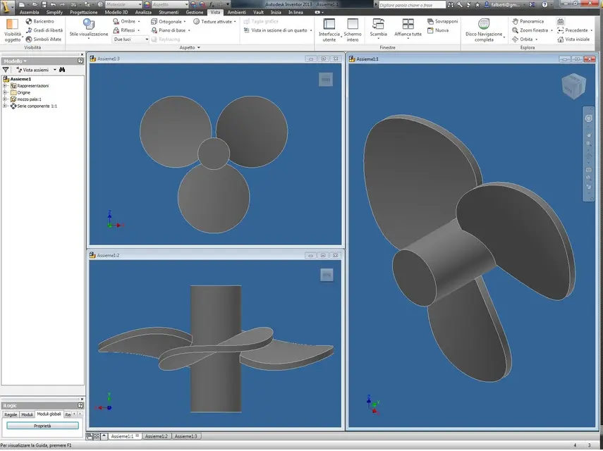
I have a marine propeller with blades with a certain shape, and once welded to the hub with a certain inclination they have to be "explained", operation that I can't perform on inventor. practically I have to have a precise inclination on the hub, then the shovel must be "laid" so that on the outer diameter I have another inclination value.

with all these words I hope you understand something, however I attach the photos of the propeller in question before the fold. ;)
 

Attachments

  • Elica 1.webp
    Elica 1.webp
    3.8 KB · Views: 31
  • Elica 2.webp
    Elica 2.webp
    4.9 KB · Views: 27
look at the image and tell me if that's how you mean
 

Attachments

  • HELIX.webp
    HELIX.webp
    59.1 KB · Views: 44
I don't think that the modelling of a propeller is like this, maybe I'm wrong, but the procedure I think is a more complex moment.
 
I don't think that the modelling of a propeller is like this, maybe I'm wrong, but the procedure I think is a more complex moment.
Yes, certainly the modelling of the propeller is more complex as you should take into account all the design parameters, however I think you can achieve results through the method I used to recreate the shovel: turning it into sheet and with the fold form. giving the values in fold degrees and increasing the bending radius.
I think it's okay, though, right? :cool:
 
if you just need to make a rough shape then everything can be fine ....
I doubt that you can do it with the sheet functions.
I don't know how the inventor quarry, I suggest you make some sections through which to pass the superifci of the single shovel and then to collect it on the hub.
to give you an idea of what the approach should look like, I put an image found on the net.
 

Attachments

  • profilop.webp
    profilop.webp
    44.4 KB · Views: 30
a marine propeller like that of serioustony is certainly not a propeller for a boat; it's more likely a propeller for a agitator or similar, too I create it from slippery sheet .
you can schematize the angle with a couple of part fold commands or with the controls in the sheet environment.
To make it more relevant to reality, you have to cuff a little more.:biggrin:
tarkus, you've caught perfectly in the sign! :finger:

the maxopus propeller is also "too much" for what I have to do:d

I already have the profile of the propeller (there is a pattern for the construction according to the diameter) and also the inclination on the outer diameter, I just wanted to understand if it was possible to recreate a blur as close as possible to reality, since to schematize it I already do an operation similar to that shown by ulantax.
 
I tried to make a svergolata shovel, however, starting from a standard part not from sheet metal, I made two slanted sketches one compared to the other of the desired angle of wintering, a little size and sewings, and I got a fairly "soft" representation of the propeller. I upload an image hoping you'll see.
 

Attachments

  • pala.webp
    pala.webp
    98.7 KB · Views: 27
I tried to make a svergolata shovel, however, starting from a standard part not from sheet metal, I made two slanted sketches one compared to the other of the desired angle of wintering, a little size and sewings, and I got a fairly "soft" representation of the propeller. I upload an image hoping you'll see.
so already it is something more pleasant, however I realized that you have to cuff a little on folds and rays, I thought there was something dedicated to doing what I meant. :biggrin:
 
but a loft with guidelines?
I threw down a very fast (very approximate) test and it seems to work. . the problem is the ends, but I think it can be solved using the surfaces.. .
when I have some time I try better working on sketches, guidelines and transitions. . .
 

Forum statistics

Threads
44,997
Messages
339,767
Members
4
Latest member
ibt

Members online

No members online now.
Back
Top