Taipan95
Guest
Good morning to all, I am a new user of the forum! I am a student at the polytechnic of torino, I attend the magisterium. I wanted to propose an exercise on dense wheels with adjoining doubts about the transmission of forces/couples: place the scheme with the data and illustrate my procedure.
 Basically, by means of a gear system, a driving power is transmitted to two different users. the doubts concern only a part of the exercise, i.e. the one that requires to identify the most stressed wheel and calculate the safety coefficient for the static verification of lewis on that wheel.
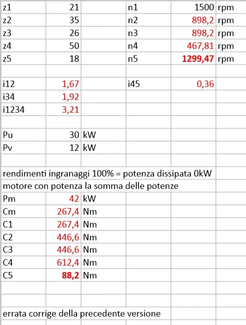
I started by calculating the input torque, placing the input power as sum of those on the two outputs: c1 = 267.5 nm.
from here c2 = c1*z2/z1 = 445.8 nm, as well as omega2 = r1/r2 * omega1 = 94.2 rad/s = omega3 since they are cast on the same tree (idem for the pair).
continuing with these formulas I came to conclusion that omega5 = 136.1 rad/s and omega4 = 49 rad/s.
Now I ask the question: the output pair, for example on wheel 4, should be calculated as pu/omega4 or as (pin - pu)/omega4? I ask this because following the first road I find two pairs on wheels 4 and 5 pairs to 612.2 and 88.2 nm, instead in the second case 244.9 and 240.2 nm respectively.
I had this doubt because I can't understand why there is no balance of couples, in the sense that (I believe) that the outgoing pairs in 4 and 5 should balance the incoming couple in 3, so the sum of couples 4 and 5 should give 445.8 nm. using the "second street" I find a result of 465 nm (however incorrect, but much more similar to what I would find using the first alternative!). in both cases the two forces (obtained as pairs / respective rays) would be 2800 and 6997 n (obviously reversed... in the first case 2800 would be of one wheel, in the second case it would be of the other) and therefore (2800+6997)*r3 would give me 445.8 nm confirming the balance. what I can't understand is whether the balance must take place for "pure" couples or for couples intended as "complete force*rage".
I apologize in advance to be extended, I thank in advance anyone who wants to contribute for patience!
Basically, by means of a gear system, a driving power is transmitted to two different users. the doubts concern only a part of the exercise, i.e. the one that requires to identify the most stressed wheel and calculate the safety coefficient for the static verification of lewis on that wheel.I started by calculating the input torque, placing the input power as sum of those on the two outputs: c1 = 267.5 nm.
from here c2 = c1*z2/z1 = 445.8 nm, as well as omega2 = r1/r2 * omega1 = 94.2 rad/s = omega3 since they are cast on the same tree (idem for the pair).
continuing with these formulas I came to conclusion that omega5 = 136.1 rad/s and omega4 = 49 rad/s.
Now I ask the question: the output pair, for example on wheel 4, should be calculated as pu/omega4 or as (pin - pu)/omega4? I ask this because following the first road I find two pairs on wheels 4 and 5 pairs to 612.2 and 88.2 nm, instead in the second case 244.9 and 240.2 nm respectively.
I had this doubt because I can't understand why there is no balance of couples, in the sense that (I believe) that the outgoing pairs in 4 and 5 should balance the incoming couple in 3, so the sum of couples 4 and 5 should give 445.8 nm. using the "second street" I find a result of 465 nm (however incorrect, but much more similar to what I would find using the first alternative!). in both cases the two forces (obtained as pairs / respective rays) would be 2800 and 6997 n (obviously reversed... in the first case 2800 would be of one wheel, in the second case it would be of the other) and therefore (2800+6997)*r3 would give me 445.8 nm confirming the balance. what I can't understand is whether the balance must take place for "pure" couples or for couples intended as "complete force*rage".
I apologize in advance to be extended, I thank in advance anyone who wants to contribute for patience!

") But in order to avoid anyone being confused by reading this post, even in the future, I felt it appropriate to state.
But in order to avoid anyone being confused by reading this post, even in the future, I felt it appropriate to state.