• This forum is the machine-generated translation of www.cad3d.it/forum1 - the Italian design community. Several terms are not translated correctly.

extrusion advice: curiosity

  • Thread starter Thread starter volaff
  • Start date Start date

volaff

Guest
Bye, guys.
a little advice.
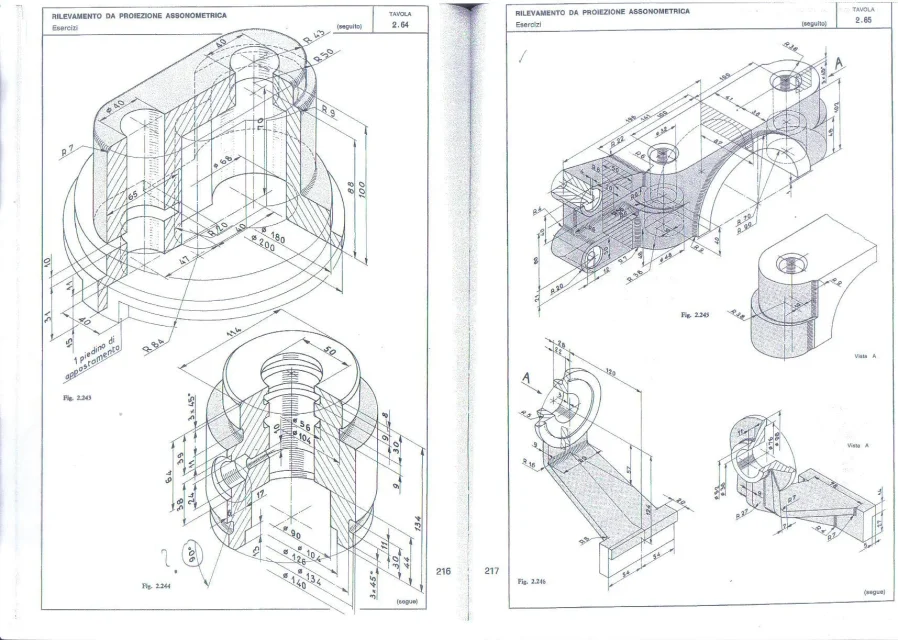
I made the cylinder circled in red first creating a sloped plane at 45° passing through the axis of the central cylinder and then creating another parallel at distance 63 mm from the axis of the reference cylinder.

the question I asked myself: is there a more practical and quick way to create lean solid bodies than the main planes?
I don't think my strategy is the only one possible.

I could, perhaps, create a tilted axis compared to the reference axis and then operate a solid in revolution.

suggestions?

thanks for the "sundation" to all.
 

Attachments

  • disegno1.webp
    disegno1.webp
    235.8 KB · Views: 102
first creating a sloped plane at 45°
Why? I see it perpendicular. . .

the method used depends on the need for the continuation of modeling and/or the convenience of using better certain commands than others.
creating axes and plans, beyond the timing that are negligible, implies that to make changes on that modeled part you have to act on multiple functions losing the snapshot that you have in changing a sketch. for example if by chance the angle change creates a geometry that cannot be solved by the axle method and planes would not see it immediately and would give you error, while with the sketch you and you could correct it visually seeing where the snare is.
right today a user has posted a body whose excavations are made all by leaning on plans and axes and points; for my whim I did the excavations with only functions because I think it is more manageable than to change the angle of the axis then the offset of the plan then the quota of the point that passes the next axis. ... this is the thread where you can see at least pictures
However, it remains a very subjective discourse that is not exempt from forced development in the definition phase.

if besides the pictures placed also the files you can see if there are other things to correct
 
we thank you for the solerte answer.
I remodeled the part differently.
Just tell me what you think.

for two three days I will not be there so I thank you already from now on and apologize if I will respond with delay to you and to anyone who wants to participate in the discussion

the version in use is solidworks 2012.
 

Attachments

we thank you for the solerte answer.
I remodeled the part differently.
Just tell me what you think.

for two three days I will not be there so I thank you already from now on and apologize if I will respond with delay to you and to anyone who wants to participate in the discussion

the version in use is solidworks 2012.
by extruding the tilted tube after the function "big cylindrical body excavations" with a sketch that does not penetrate the inner hole you can not completely encapsulate the new function in the main body making unfair the realization of the fitting unless you complete the gap with two additional extrusions and if you move the edge of the sketch rectangle to the inside you have part of the cylinder that leans you into the inner hole. to solve three or four problems in one shot only it is sufficient to move the construction plan of the small cylinder sketch and then the relative function of revolution of the small cylinder before the cutting of revolution that creates the internal dig to the big cylinder having the firmness to put the flag on "join result" otherwise the 8 mm fitting can not do so.
it takes more time to read this message than to make the change. I made you a video because I have the 2013 banner and you couldn't open the file.[video=youtube_share;Lb0S4RhCCqE]https://youtu.be/lb0s4rhccqe[/video]
 
beyond what is said by marcof I add small notes that I think simplify modeling.
- the romboidal base can do it in a single function by drawing a rombo (with the command of parallel sketch) which has the vertices united by lines of construction, these relations with the origin by selecting all three entities and selecting intersect as a relationship. After that you do the ray. so eliminate the two mirrors
- the unique puncture then mirrored not if you can see... the usual mirrors for complex situations not for a hole that makes it two clicks in the sketch. above all the holes if possible fall with the hole wizard function, even the simple holes not threaded; this because you don't have to draw anything but the points of the centers making the sketch simple and fast, if you have to make a repeat based on those holes you can use the sketch of the guided drill; If you need to insert viteria in a set, or else in those holes you can use the function that containing the sketch points will repeat n points.
- I don't remember this, but I still call it. if already existing in 2012 you can use the connection function to multiple rays. check between function and guide options
- on the double function to make the two cylindrical bodies according to me at least the second can be done in a single function without with this hanging the sketch. but it is a subjective method.
- very important: when you do the revolutions quote the diameters taking as reference the axis of revolution so that you can give diametric measurements without having to do the calculations for the rays (which until they are round measurements is fine, but if the decimals begin not to mention inches are pains) this allows you to have under eye the actual measures both for modeling and for any changes.
 
thanks for the precious advice.
as soon as I return, I answer calmly for any doubts.

Have a good day! !

Thanks again. ! !

edit for marcof: thanks for the video. on another location I have a more recent version of solidworks so even with the file it was okay (and for you it was more comfortable).
Thank you for the time you both dedicated to me.
 
Good evening.
Thanks again for the video.
In fact, as I modeled it, I should have re-made the internal cut.
what I didn't think of was to move the features so that the cut was done once only.

I also did 2.62, I would like to know if I made serious mistakes according to you,
In addition, do you think the parts marked in blue should be collected? ? ? ?

tips for modeling 2.241? ? ?
I have the feeling that a quotetype lacks the diameter of the large horizontal cylinder.

Thank you all.
 

Attachments

  • 2.62.rar
    2.62.rar
    131.1 KB · Views: 6
  • disegno1.webp
    disegno1.webp
    557.7 KB · Views: 44
I also did 2.62, I would like to know if I made serious mistakes according to you
following your modeling methodology I would have:
  1. omitted the " rectangular base cut" by incorporating that processing directly into the sketch4 of the previous processing
  2. chosen as a sketch plan of the " longitudinal hole cutting" the lower face of the cylindrical body in order to make a single passing cut without having to choose the second direction
  3. for the same principle of point 2 the sketch of the rectangular base cuts I would have made them on the external face of the parallelepiped so as not to have to choose the discord direction. alternatively, leaving at points 2 and 3 the plans you chose, I would have made a cut according to the middle floor setting a superbundant value
  4. I would have done it with a simple rectangular sketch on the upper face (where there are holes) and then I would have added after the two triangular excavations
  5. eye that the two holes diameter 6 you made them pass while they have to peel only in the cylindrical hole diam.35
of course my considerations are made on a model made, so I benefited while if I had done it from scratch maybe I would have used double of your features :smile:. the only one you can save is the one specified in point 1. the use of the two cutting directions allows you to use the main paini of the model but at least use the cut with the intermediate plane that you click half for each feature. I personally am lazy and, unless there is really the need to use the main paini, in cases like these I put myself directly on the faces to cut.
In addition, do you think the parts marked in blue should be collected? ? ? ?
apart from that it would be impossible geometricamtne (unless to make a delirante round hole from a square hole with four fittings). Those traits are shadings to highlight that it is a circular face.
tips for modeling 2.241? ? ?
I have the feeling that a quotetype lacks the diameter of the large horizontal cylinder.
the diameter of the horizontal cylinder corresponds to the external width of the two perforated brackets (56 mm) see it to the eye where the edges of the external face end at the axis of the cylinder and the external faces are tangent to the cylindrical body.
I would do like this:
  1. horizontal cylinder pieno:rolleys:
  2. plan tangent to the cilindo
  3. horizontal top of the cylinder axis
  4. Extrusion of the sketch inside for the thickness of the bracket
  5. mirroring the bracket on the other side
  6. creation of the average plane of that species of semiboccola at distance of 120+12 from the cylinder head
  7. 24 mm body profile design and extrusion with "intermediate floor" option
  8. extrusion of the connecting body starting from a diegnato rectangle on the floor at point 6 with the two lower tangent vertices to the circular section of the lower cylindrical body and the two uppers coincide with the outer edge of the semi-boccola
  9. central hole cutting of the cylindrical body (now is the time to do so :rolleyes: )
  10. fittings
should be 9 or 10 feature depending on whether the fittings are all the same or there are two different measures, as it would seem to the eye.
 
- very important: when you do the revolutions quote the diameters taking as reference the axis of revolution so that you can give diametric measurements without having to do the calculations for the rays (which until they are round measurements is fine, but if the decimals begin not to mention inches are pains) this allows you to have under eye the actual measures both for modeling and for any changes.
How can I quote the diameters in revolutions if, in fact, I take the measure back to the axis of revolution?? in the 360 ° revolution I always go to quota the ray, or am I wrong? !

good start of the week to all.
 
perfect now I understand how to do thank you for the straight.
I tried to use this "command" to make the piece in the figure.

the piece is similar to what ran me marcof but there is a quota that I cannot understand what it refers to (and I don't know if the profile of the cut in revolution is correct).

I can do the other.

Greetings to all boys and thanks again.
 

Attachments

  • lastscan.webp
    lastscan.webp
    320.3 KB · Views: 22
  • 2.2444.rar
    2.2444.rar
    118.9 KB · Views: 4
the first two functions you can join them.
for the side hole I do not see the reason to do it at 45° and therefore make the appropriate plan. you can do it on the right or front or give it the height position on the sketch. Moreover in the sketch put the quota from 45 (act that in fact does not exist) from the point on the origin to another and creating it projected. in these cases better select a line and a point to have the desired size. but you have to put the 90° angle I told you in the previous post
thanks to the advice but I lost on "creating it projected":)
 
I guess, but I didn't know how to explain. if you see in the image your share from 45 is compared to the orthogonality of the sketch. that in red is orthogonal quoted from the line to the point. if you put instead the 90° already said will have to be as value ortogonale 40Immagine.webp
 
I guess, but I didn't know how to explain. if you see in the image your share from 45 is compared to the orthogonality of the sketch. that in red is orthogonal quoted from the line to the point. if you put instead the 90° already said will have to be as value ortogonale 40View attachment 44145
perfect now I realized by doing it on the sketch.
for the rest the other quotas should be right.
only one question: how could I do to create that tilted hole on the front plane (for example)? ?
then would I have no problem on the 64 distance between the upper edge and the axis of the sloped hole?
 
I think he's not inclined at all.
I meant that the hole axis is tilted to the front floor.
If I went to make a sketch on the front floor, I wouldn't be able to make that hole.
This is why in order to realize the hole I created a 64-phal upper edge distant plane by tilting the axis to 45 degrees.
 
I can't see a quota indicating that the hole is inclined to 45°.
even because if there are no other reference machining on a cylindrical piece, the hole at 45°, 32,6° or 90° changes nothing.
Can you tell me the portion that defines the hole position?
 
I can't see a quota indicating that the hole is inclined to 45°.
even because if there are no other reference machining on a cylindrical piece, the hole at 45°, 32,6° or 90° changes nothing.
Can you tell me the portion that defines the hole position?
in reality the quota "fantasm" of 45 degrees is not on the drawing.
The problem is that I don't understand how to make that hole with a sketch on the right or front.

I hypothesized that the axis of the sloped hole as I do not understand how to realize it if not with an auxiliary plan as I did.
I don't know if I could explain.
 

Forum statistics

Threads
44,997
Messages
339,767
Members
4
Latest member
ibt

Members online

No members online now.
Back
Top