I see that you have extruded by changing the axes compared to my file, I think it is a problem because to me the section always horizontal or all at the same altitude in z while the guide line has to be of different z
That's what comes out of me.
the problrma is that the guideline and a 3dpoly so it can have all the different z points.
in my example I took point 1 of the guideline and I brought it to altitude -30 because before it was too horizontal maybe it confused ideas.
to me the section goes horizontal then not correct and then extrusion on trajectory
He doesn't want a flat extrusion. otherwise it would have been enough to flatten the pline3d (without even bothering the geompiatta, it was enough to recalcate the pline3d with a pline2d).
he wants the extrusion path to be in 3d, along the pline3d.
but when you go to extrude, just because of the long z variation, in the autocad curves (correctly) the geometry to be extruded, and the resulting solid "sell" from its verticality.
And he doesn't want that.
This would take someone who knows about autocad.
we call a, b, c, d, and f the various vertices, starting from to the nearest one in your view and f the farther.
in the left solid, leave correctly from to until b, then b-c barks and remains disembarked until f.
in the right solid parts already disembarked from to until b, still disembarked b-c, then straighten you until f (as if you had extruded from f to a).
in the right solid then there is an extra piece in a while in f the solid does not end perpendicular to the path, but with a tilted section in the plant.
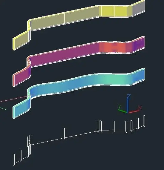
if it is not strictly binding to follow the pl3d, you could use loft, after placing some sections, first on the extremes and in the middle points of the individual strokes, and then possibly infitting them, especially in curved sections, to increase accuracy.
3 cases, starting from the bottom, correspond to 3 loft options, smoothed, normal to all sections, lined.
No. both solids are wrong.
one because it disembarks ugly (the one left), the other because it disembarks the same (less, but the same) on the sloped tract and has an extra piece.
moving the extrusion section from the other head also has another negative effect.
the height of the extrusion shape, measured from the center of the arc below the middle of the upper face will be a certain distance.
When you extrude by reversing the starting point, in the tilted part (what I called at the point) the section will be perpendicular to the extrusion path, but this means that the vertical component (i.e. the original height value) in this area will be greater.
At this point I think the best solution is that suggested by joseph when citing using the loft command by placing the sections along the extrusion path.
Oh, here we go. Sorry for the absence, but I see that in 4 days you have gotten off to look for solutions.
So, the way (the only way) to solve the problem of meacmea is this.
you take the initial section and copy it with the center of the arc below (the one in which the plinea3d begins) in all the vertices of the straight traits.
now, for pure comfort, we change color to the original section (let's make it red).
we copy the new red section, with the same starting point as before - center of the arc) in all the vertices of the beads representing the curves.
We will have, looking in the plant, a series of sections that however will not be oriented well because they must be perpendicular to the pline3d in every point.
for each "curve" fitting of the beads, we create in circle for 3 points taken on the existing curve (this will give us the center in the xy plane of the curve).
We do not care that the points taken will be different, we are working in global ucs and the z of the circle center will be the z of the first point taken, but we do not care.
Let's put in plain sight and one by one, we roar the red sections by using the "wheel" command with "reference" option.
when acad asks the point of rotation we will take care to select the center (even if we have to force it manually).
It's true that we see a line on video, but autocad will take the center of the section arc as a point.
giving option "reference" acad will ask for the first point (again the nod of the arc) and second point (an end of the section, no matter which), then ask for the destination point and take the center of the circle we created.
as we are working with global ucs, the z differences that autocad will fall into the points will not be considered. according to that autocad plane can rotate the object exclusively along a trigonometric circle lying on the xy plane, rotations in the xz and yz planes are not allowed (unless to use the wheel3d command, but we will not use it).
done this, looking in the plant (command _plan), we will have our pline3d with so many perpendicular lines to the beads in the direction changes, as if it were a worm with rings.
of course we will check if even the beginning and end of the straight strokes are perpendicular to the beads. if they are not, we will rotate until they are (the method I have already explained).
Let us put in a 3d view at will, let us distinguish all the true copied sections.
We'll see a solid wireframe symilmodel, but it's just a series of sections positioned along a path.
at this point comes the enormous simplicity of getting the solid.
_loft command, you select all sections, one by one, in the exact order along the pline3d.
the option will be "only sections" and the type of surface will be "regatta", without any connection.
I already know that a friend waited for this answer and told him: Now you'll have fun! :biggrin:
Let's just hope they don't ban me for too much length of the post!
in practice have you positioned a profile at the beginning and end of each beads and at the beginning, end and center of each curve along the beads and got the solid through the loft command? Do I understand?