• This forum is the machine-generated translation of www.cad3d.it/forum1 - the Italian design community. Several terms are not translated correctly.

extrusion rectangular and elliptical profiles

  • Thread starter Thread starter delphy90
  • Start date Start date

delphy90

Guest
Hello, everyone.
I am a boy enrolled in engineering at the first weapons with solidworks (work with the 2013 version).
are struggling with the cad design of a uav but I am experiencing some difficulties in modeling between the different sections.
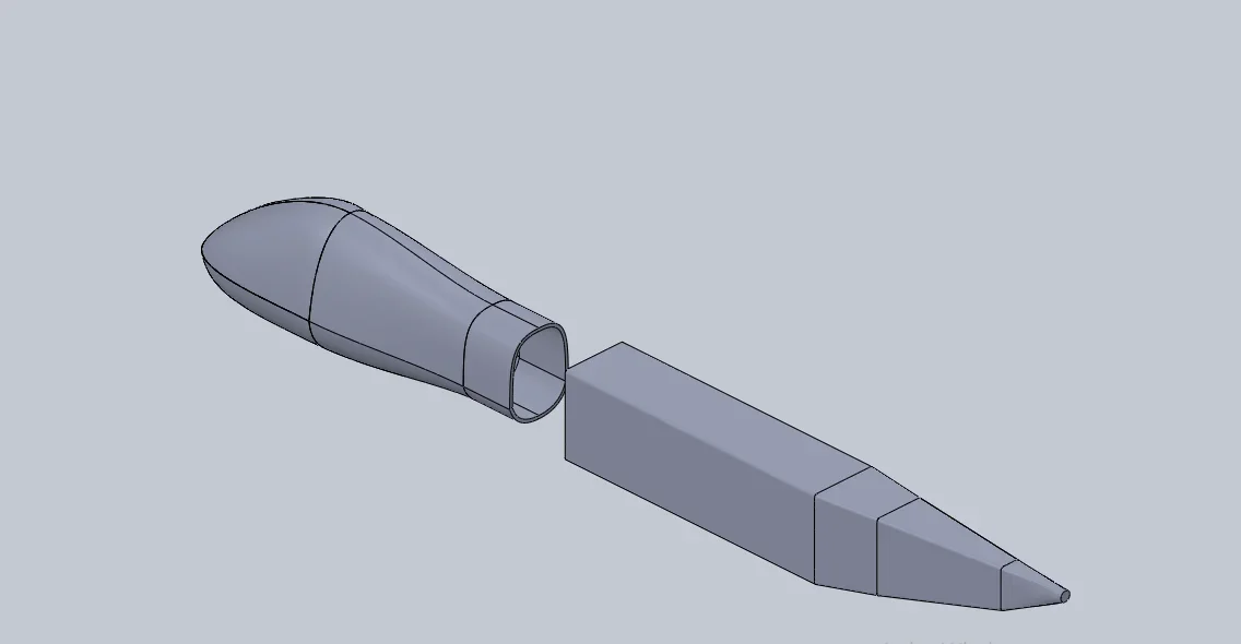
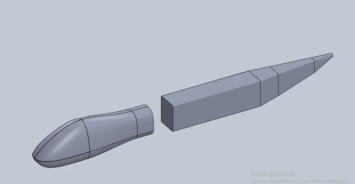
in the attached file, you see in a set the two pieces that I have to mate. the two sections are different geometry.

do you recommend which function to use to create a certain continuity between the two parts?

Thank you all for your help!
 

Attachments

  • Assonometria1.webp
    Assonometria1.webp
    13.1 KB · Views: 16
  • Assonometria2.webp
    Assonometria2.webp
    9.7 KB · Views: 18
You should use the loft, but tell us what it's like to go from a hollow section to a full one?
if you are in the beginning do the internal tutorials to the program where the basic and advanced commands are explained
always attach the file to give the possibility to those who try to help you verify the model, geometry and feasibility of the proposed solutions.
to me turn out your posts from the end of 2016... have you had no way to learn basic commands since then?
 
Thank you very much for the answer:)

I share with you when you say that it doesn’t make sense to go from a full side to a quarry.. But I don’t know how to make full even the nose of the uav..following tutorials on youtube I managed to faithfully reproduce the muzzle of the predator creating surfaces that I later thickened. I didn't know how to create a solid from a set of surfaces. Do you have suggestions on how to make it full?

I tried to combine the two parts with a loft but it creates an asymmetric geometry.

in the evening I also attach the files so you know to recommend better.
 
following dei tutorial su youtube
Did you do that?
it is not that just because on youtube there is written tutorial means they're good. or I am, but they assume a basic knowledge that those who see him do not possess.
first do the internal ones that start from scratch and make a logical progression giving a stick of the tools and how to use them, then, only then, do those found here and there to broaden, curiosare, experiment
 
I did, but believe me, with the loft geometry is obscene.

I attach the files so you can give me some advice to the following questions:

1. how do I thicken muzzle surfaces as an alternative to thickening function?
2. how to create a volume of connection between the two sections (mouse and fuselage)?
 

Attachments

I strongly recommend you to remake the tutorials because you did not understand the logic of solidworks.
first of all in the zip there are two files and not one as you desume from your images; Which means you want to build the missing piece from a set. already do not know that in the environment together there are no functions of creation bodies is severe. if you thought you would do it by inserting a blank part and managing derivative sketches with a minimum knowledge of the program let it go. among other things you have not even attached the aid with the details inserted.
this in the tutorials may not explain it, but the fittings and all finishing functions should be inserted, unless necessary, at the end of the functions

the particular fuselage has the first useless loft function as it is a simple extruded rectangle; you did 4 loft functions when with a bit of precision and some guidelines were enough 1.

in the particular fuselage, in order to be able to handle a similar geometry you must be as clean as possible in order to manage only what is necessary.
First of all, underdefinite sketches are the antithesis of modeling 3d and are the first step to have suits possible and unmanageable.
you have to use the commands available and know what you want to get; it makes no sense to start creating the body at the end of all surfaces if the model is symmetric, then after surface-filled4 where you have half fuselage you make a nice merge surfaces, adding two more to close the box, and you get, with the appropriate option creates a solid body, one half model body (and you delete, from the surface folder, all the hidden surfaces that you do not need at all)
at this point mirrors the body

done all this to make the central part between the two components you use the loft and add guidelines to manage well the variation of the profile
 
Thank you very much for the detailed answer. thanks to your advice I modified the initial part of the muzzle.

That said, I keep having problems with the loft and guidelines to manage the variation of the profile. Apparently, the function doesn't recognize me (it doesn't even highlight the sketch) and I can't understand why.

Following your advice, I decided to continue to create the rest of the fuselage in the same part where I started to create the muzzle. In this way I avoid doing a set.

1. What problem do you encounter in creating the guidelines that will serve me for the loft? ?
 

Attachments

the curvecomp1 function is useless.
the loft does not necessarily need to have sketches, you can well do between faces or between faces and sketches
So the loft is feasible and I don't understand what you mean by I don't even notice the sketch and I would say that if I've been detailed, you should be pointing out which sketch does not select you as the sketch37 selects it quietly.
the guideline has a problem, but as mentioned above you have to be detailed and specify which problem results to you. if it is what appears to me when I confirm the function (with appropriately selected profiles) is specified in the error message that appears, if instead it is another until you tell us we can not know what it is.
I repeat that you see that you lack the basics and that you do not read the guidelines of the functions you are using
 
I try to be detailed:

when I use the loft function by selecting the external face of the muzzle <1> and the sketch37 adding as the guide curve the sketch39 appears the following message
"curve 1 is not valid because it does not intersect section 1". What do you mean? ? ?

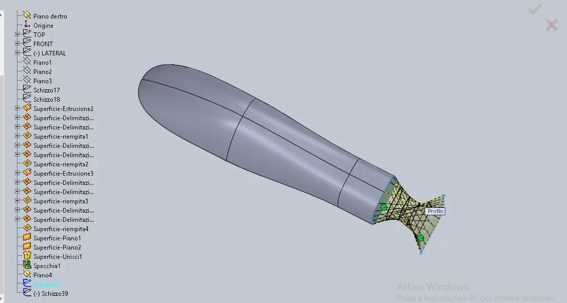
if instead I don't insert any guideline, it creates a profile like that in the image below. is not exactly the best geometry. How do I improve this error?

what features should the guideline have for optimal geometry?Loft_fusoliera.webp
 
curve 1 is not valid because it does not intersect section 1".
first of all you have to understand what your section number 1 is and you understand it from the profile tree
then you have to understand what intersect means and here should not be difficult.
do these two steps you have to analyze the sketch of the curve and fix it.
if instead I don't insert any guideline, it creates a profile like that in the image below. is not exactly the best geometry. How do I improve this error?
that is not a mistake, but how geometry is interpreted with the data you gave it. If you look at the preview there are two green balls... Did you try to touch them and see what happens? on sketches instead of lines you can select points to establish a connector while for and other usable entities (faces and edges) this for obvious reasons is not possible
 

Forum statistics

Threads
44,997
Messages
339,767
Members
4
Latest member
ibt

Members online

No members online now.
Back
Top