
Conte91
Guest
Hello everyone,
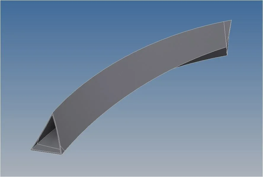
I find myself having to get the development to build what you can see in the image.
3 developments that will then be welded (don't ask me how they bend them assured me not to worry)
to get the development (inventor 2016) I wanted to get my external face (or a body with uniform thickness that is only a plate of 3) to select it and convert it into sheet metal.
Let's say I'm already banging my head to get rid of an edge that in my opinion should not exist. .
I created a sweep extrusion with a triangular profile and a "path" consisting of 3 arches, 1 making almost all length and the other 2 small to the extremes (the same center radius and complanaries {even if created in a 3d sketch})
in the sweep function I inserted a twist of about 80 degrees. .
the edge therefore is created by the division of the arches that make up the "track". .
It's not the first time I'd like to use surface controls with inventor, and every time I don't jump out. .
Anyway, would you tell me if it's possible to do what I want to do with inventor?
I tried to attach the 3d, but it's a derivative part and it doesn't charge me in step ne iges...
thanks in advance
I find myself having to get the development to build what you can see in the image.
3 developments that will then be welded (don't ask me how they bend them assured me not to worry)
to get the development (inventor 2016) I wanted to get my external face (or a body with uniform thickness that is only a plate of 3) to select it and convert it into sheet metal.
Let's say I'm already banging my head to get rid of an edge that in my opinion should not exist. .
I created a sweep extrusion with a triangular profile and a "path" consisting of 3 arches, 1 making almost all length and the other 2 small to the extremes (the same center radius and complanaries {even if created in a 3d sketch})
in the sweep function I inserted a twist of about 80 degrees. .
the edge therefore is created by the division of the arches that make up the "track". .
It's not the first time I'd like to use surface controls with inventor, and every time I don't jump out. .
Anyway, would you tell me if it's possible to do what I want to do with inventor?
I tried to attach the 3d, but it's a derivative part and it doesn't charge me in step ne iges...
thanks in advance
 Can I not create a surface directly from a face?