• This forum is the machine-generated translation of www.cad3d.it/forum1 - the Italian design community. Several terms are not translated correctly.

fem composite bicycle frame

gaz89

Guest
Hello everyone,
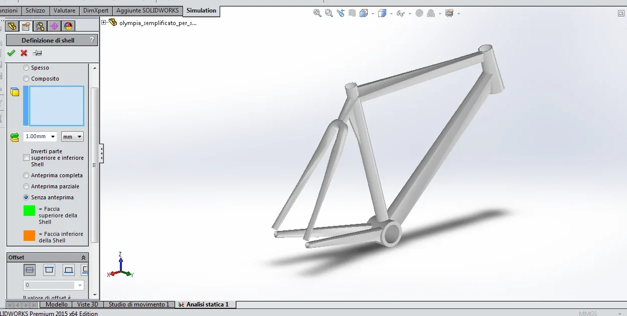
I am a student of ing.mechanics and for a fem project for a university course I decided to do a static and dynamic analysis (simplified) of my olympiaiq monocoque racing frame (I am also a cycling enthusiast).

I have reproduced the frame in solidedge, trying to respect the most various geometries. for fem analysis I would like to use solidworks 2012.

I have already "tested" the frame considering it in aluminum 7075 only to verify the correctness of the geometry and therefore the possibility to create mesh and subsequently stresses, movements etc.
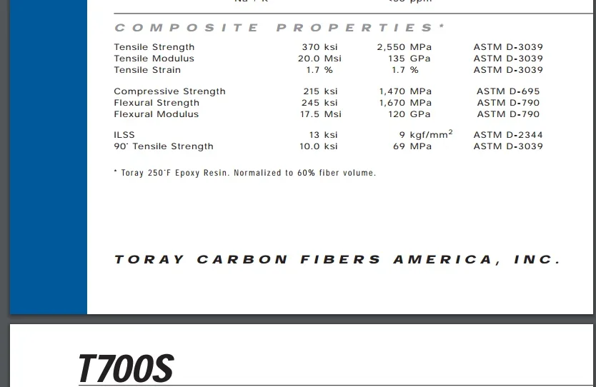
Verified geometry now I would like to remake the simulations considering as a basic material a composite (torayca t700s). I know that this type of simulation is very different and more complicated, to simplify and not to use shell models I could only consider in my custom material (orthotropic material) the values of the mechanical characteristics I found for the composite(torayca t700s)?

Thanks :)

attach frame image and material data sheet.
 

Attachments

  • olympiaIQ.webp
    olympiaIQ.webp
    77.4 KB · Views: 27
  • t700s.webp
    t700s.webp
    29.7 KB · Views: 13
  • t700s_1.webp
    t700s_1.webp
    34.6 KB · Views: 10
As for static and dynamic behavior, approximation you could do as you say.
but it's worth putting on hisotropic properties. the bicycle frame is a tube structure, so with good approximation, when you put the correct elastic module in the direction of the tube you are already next.
keep in mind that the mechanical properties you need to put are not the lamina, but the laminate properties. which is composed of fibers oriented in various ways. so from 125gpa you easily descend to 80gpa. the resistance of 1570mpa is only from laboratory tests, moreover with the laminate the value drops much, then not modeling the individual skins, I think it is useless to think of determining stress. I think the result can only be valid for deformation.

in universities use ansys that has a nice composite module, you should take the shell and use that.
 
Thank you very much!
therefore I will proceed considering the isotropic material.

the problem is that even if you want to proceed in the correct method I do not know how many layers of skin are used, it seems to depend everything from company, frame and performance required. Thank you again:)
 
if you do not know the laminate you do not know the thickness of the tubes and the elastic module. then you are completely random
 
if you do not know the laminate you do not know the thickness of the tubes and the elastic module. then you are completely random
I know... but unfortunately I can't find anything online. ok geometries and type of composite...but something more accurate about the real manufacturing process nothing.
 
What you will get is a pure university exercise, but it would be better to stay on aluminum and not on composite, you have too many variables that you do not consider and you know too little.
that is a shell pattern with composite blades.
or shell for aluminium. made with solid elements, it is not exactly the maximum,. if you then mortgage the properties without knowing how it is done, it becomes a pure univiersitario exercise.
ok then proceed considering (with the simple purpose of an exercise) aluminum alloy 7005 with uniform thickness of the walls of 1.5mm.

Can I ask you one more advice? for static analysis I have seen some use fixed geometry constraints on the rear hangers, instead in a tutorial I have seen instead apply bearing constraints on the rear hangers and on the steering tube an elastic bond with a high rigidity to simulate the wheel.

Any advice?
Thanks :)
 
isostatic binding. Whereas vertical z:

for example xyz on the front fork, yz on the rear fork, y to the handlebar (or to the upper hub).

in this way you should be able not to give additional stiffness due to constraints
you should put the bond on an intermediate node to the fork, on the frame symmetry plane. I don't remember if you can do it in sw2012
 
Hi, I don't know if to open a new discussion, but I think it's not necessary since the basic argument is always the same.

However using the shell analysis I have a doubt, sw automatically calculates the average surface of the faces? because having tubes with a somewhat more complicated geometry I should do a section and select internal and external face one for a...maybe it is useless to do it. Thank you!

then, for example, in the image by clicking the upper surfaces I will have the intermediate surface directly?
Thank you!
 

Attachments

  • sw_telaio.webp
    sw_telaio.webp
    41.2 KB · Views: 12
you can extract the outer surface and tell the fem to put the thickness offset inside, it is not accurate how to work on the average surface, but you save a lot of time.
 

Forum statistics

Threads
44,997
Messages
339,767
Members
4
Latest member
ibt

Members online

No members online now.
Back
Top