• This forum is the machine-generated translation of www.cad3d.it/forum1 - the Italian design community. Several terms are not translated correctly.

flag crane size

  • Thread starter Thread starter Dutch Mauro
  • Start date Start date
what I wanted to say is that we are in front of a normal eccentric sforzxo so in the sez. we call it a-a (at the base) you have mf+compression. then you can solve it with the omega method.
max= mfmax/wf + omega*f/a <=sigma amm.
(if I wrote right).
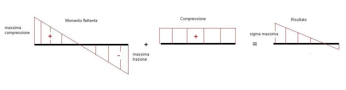
ok understood therefore I have a case of pressure + bending. ..the formula I know... only that I used it without omega (but I went to read on the internet and Omega from what I understood is to mean the eccentricity true?why is it worth? ). . .
 
no need to use omega. the effort from moment is to butterfly (if you know it means well, otherwise do not search on the internet! or you look for it on the book, or we explain it to you)
to this butterfly, put the constant pressure from normal effort and get the new maximum sigma.

to this then must be added the weight of the beam and the weight of the column, they are not bruscolini, we do not neglect them. . .
I'm sorry for my ignorance, but I don't know what a butterfly moment means. . .
 
no need to use omega. the effort from moment is to butterfly (if you know it means well, otherwise do not search on the internet! or you look for it on the book, or we explain it to you)
to this butterfly, put the constant pressure from normal effort and get the new maximum sigma.

to this then must be added the weight of the beam and the weight of the column, they are not bruscolini, we do not neglect them. . .
but why not use the omega method? is it not a simplified method to solve the problem of peak loads?
 
but why not use the omega method? is it not a simplified method to solve the problem of peak loads?
In fact, in the dispersion it is generally not considered instability, because there is finite devolution before the plastic collapse.
In practice, if peak load can happen that the compression theory beam bears a load, but in practice before that load goes into instability. If there is a considerable moment, the sizing at this moment keeps far from risk of instability.
I looked at the omega method and understood it... and then?
Wow... you're a genius! I at the third year of university spent two months understanding it, along with the criterion of eulero!
 
In fact, in the dispersion it is generally not considered instability, because there is finite devolution before the plastic collapse.
In practice, if peak load can happen that the compression theory beam bears a load, but in practice before that load goes into instability. If there is a considerable moment, the sizing at this moment keeps far from risk of instability.


Wow... you're a genius! I at the third year of university spent two months understanding it, along with the criterion of eulero!
thanks x the easy irony... the term understood was about to know what you are talking at least...:smile:
 
In fact, in the dispersion it is generally not considered instability, because there is finite devolution before the plastic collapse.
In practice, if peak load can happen that the compression theory beam bears a load, but in practice before that load goes into instability. If there is a considerable moment, the sizing at this moment keeps far from risk of instability.
I get it. but as you have realized, you have to try to make things simple. I remember that at theitis there were problems of this kind and one of the methods adopted to solve them, it was precisely the verification to point instability through the Omega method. In the end, we were studying as experts, not yet as engineers. :biggrin:
Yes, it's been many years, we haven't talked about limit states and we still used fe42...
I still see it hard. .
ank I see it hard... but a very important thing believe me... I have to deliver it Thursday and I am beginning to understand a minimum now... help?!? ! ?
 
I'm sorry for my ignorance, but I don't know what a butterfly moment means. . .
If you have a beam currently, in each section you have a certain distribution of internal tensions. are all sigma type, i.e. traction or compression (the cut is usually negligible).

consider the column and consider only the flender moment. the left fiber is in traction, the right one is in compression. As you move towards the center the tension decreases, until you reach a minimum in the so-called neutral axis. for sections with multiple symmetry planes (such as ipe, hea, circulatory, etc.) the neutral axis passes through the intersection of these, and therefore for the center of gravity. for a t for example does not happen. you can calculate, but let's forget, it's not trivial.
Sorry to paint, but I didn't find anything better on the internet.

now, add the compression that is added to this diagram. get the right diagram. the maximum voltage is given by the maximum bending sigma and the compression sigma.

add the weight (in n) of beams and column, divided by the column section area, and get the maximum compression sigma acting on the most stressed section (the column base) on the internal fiber. you need to dimension so that this sigma is equal to y/s where y is the yielding voltage of your material, and s your safety factor.
 

Attachments

  • Farfalla.webp
    Farfalla.webp
    11 KB · Views: 54
If you have a beam currently, in each section you have a certain distribution of internal tensions. are all sigma type, i.e. traction or compression (the cut is usually negligible).

consider the column and consider only the flender moment. the left fiber is in traction, the right one is in compression. As you move towards the center the tension decreases, until you reach a minimum in the so-called neutral axis. for sections with multiple symmetry planes (such as ipe, hea, circulatory, etc.) the neutral axis passes through the intersection of these, and therefore for the center of gravity. for a t for example does not happen. you can calculate, but let's forget, it's not trivial.
Sorry to paint, but I didn't find anything better on the internet.

now, add the compression that is added to this diagram. get the right diagram. the maximum voltage is given by the maximum bending sigma and the compression sigma.

add the weight (in n) of beams and column, divided by the column section area, and get the maximum compression sigma acting on the most stressed section (the column base) on the internal fiber. you need to dimension so that this sigma is equal to y/s where y is the yielding voltage of your material, and s your safety factor.
here is the right explanation, actually rereading here:http://www.cad3d.it/forum1/showpost.php?p=128056&postcount=36 I had not been absolutely clear, indeed...
 
I think exatem meant that by rereading his post (the link) he did not seem sufficiently clear. . .
 
Sorry but in the link you put there is no explanation
in that post I said that the mf manifested maximum at the base of the column. In fact, as the Roman fulvio rightly says, the stress on the subject is the sum of the mf and the compression effort.
 
Good evening to all, my name is pietro I attend the last year of wedge itis and I need some tips... .
I have to design a flag crane considering these data:
lifting height h=3m (meters)
max liftable load q=5000n (newton)
sbraccio l=2.5m (meters) [dall'asse]I calculated the binding reactions of the structure, I drew the chart of the moment and the cut.
I need to know what type of section to use for the horizontal beam (for vertical use a circular section) and the stresses that act on the horizontal beam.
Who helps me? ? ?
thanks in advance
 
Hello _pietro_,
So much to know... did you read all the thread? The question is the same as you do, will it be your partner? there are also six pages of comments. . .
 

Forum statistics

Threads
44,997
Messages
339,767
Members
4
Latest member
ibt

Members online

No members online now.
Back
Top