• This forum is the machine-generated translation of www.cad3d.it/forum1 - the Italian design community. Several terms are not translated correctly.

for tristan <solaio cementizio="" latero=""></solaio>

  • Thread starter Thread starter mario cant
  • Start date Start date

mario cant

Guest
in performing when reported in http://ctrl-alt-cad.blogspot.it/2014/09/solaio-laterocementizio.html I found the following problem:

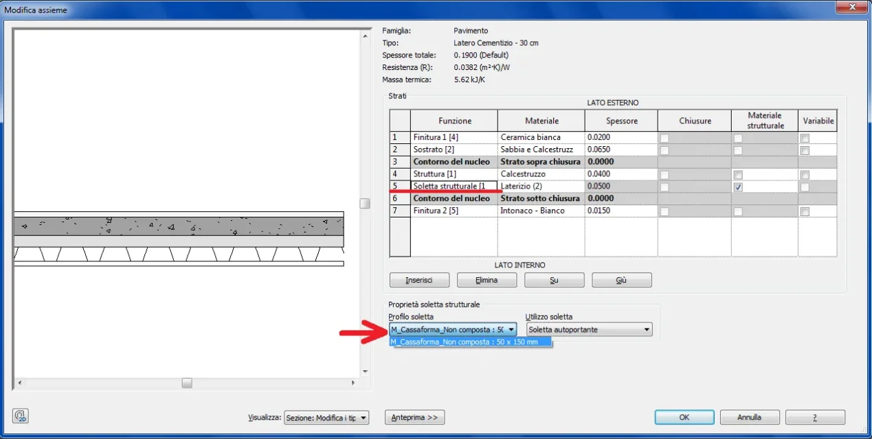
created the profile as described and loaded into a project, when I then go to change the structure of the structural floor with the structural insole [1] in the “modifies together” window in “insole profile” I do not see the profile I created and uploaded in the project, but only the default profile is available.
How come? ?
I believe that I have done everything correctly in the recalled article I am less than there are underintensive things .... and not explicit
 

Attachments

  • solaio.webp
    solaio.webp
    55.9 KB · Views: 34
the profile family was built as indicated in the article

Anyway..... how do I attach the file?
 
I had already tried ....as for the pictures....but it signals error of ‘’ invalid file’’.
I supported the file in an external position
Here is the link: http://dropcanvas.com/#205c4i85jz0eiz the attached file is of the project in which the profile was loaded.

of course for the family profile:
browsers > families > profiles > loft
 
That was...
I caught you in foul :tongue: .... is a detail to add / clarify in your article.

Tell me something else:
If we sections the loft in the orthogonal direction at the edge, we will see the morphology of our loaded profile, and therefore will result a very detailed section.

while if the section is made in the parallel direction of the ornamentation you do not see a h.....i.e. the section is of the "normal" type, so I wanted to ask you there is a way to see also in the section parallel to the warp a something more detailed that is not the simple restraint, and however conform to the family of the profile that has loaded
Hi.
 
if the section is made in the parallel direction to the ornamentation you do not see a h....
and that is right, at least in this type of loft. the beams and the pignatte follow the direction of the ornamentation, they do not cross. . .
 
I take this post for some problems:
I created the profile (which as clarified) must be opened.
1 - I have uploaded to the project but it happens that the profile does not take into account the wall that perimeters the structural ceiling, the same profile continues beyond the wall. as seen in the image.
How to solve the problem?Immag Solaio.webp2 – when I created the profiles I created parameters, including one to manage the width of the beam. the parameters inserted are of type.
Now the loft (structural or architectural) is a system family, so how can you adjust or manage the profile parameters within the project.
in other words how to change the parameters, created for the profile, within the project??

3- in the recalled article http://ctrl-alt-cad.blogspot.it/2014/09/solaio-laterocementizio.html in the last image at the bottom, you can see the loft in the section in which there are two pignattes designed in detail with all the holes.
How can these holes be added?
in the sex profile family I tried to draw other open profiles, representing the holes but it does not work....
Thank you in advance
 
1 - I have uploaded to the project but it happens that the profile does not take into account the wall that perimeters the structural ceiling, the same profile continues beyond the wall. as seen in the image.
How to solve the problem?
Are the walls connected to the floors?
how to change the parameters, created for the profile, within the project??
creating appropriate types of floors
3- in the recalled article http://ctrl-alt-cad.blogspot.it/2014/09/solaio-laterocementizio.html in the last image at the bottom, you can see the loft in the section in which there are two pignattes designed in detail with all the holes.
How can these holes be added?
with repeated detail components
 
1- no in fact the walls did not join the floors, they are simply connected, the first ones, to the floors. by default
I thought it was automatic....instead you need to manually merge walls and floors!

In this regard, does this problem arise from the size of the profile in its relative family ?
i.e. regardless of the size of the profile, the same will fit the size h height and the length of the ceiling.

2- forgive me, what do you mean by:
"creating appropriate types of floors". Could you specify?
I listed the profile: width, height, beam switch, which then became type parameters, did this I loaded it into the project.
in the project, then, duplic and published a type of floor already existing, and in this modifies the existing layer that corresponds to the part in cls and pignatte...... as indicated in the article


3- even here I do not understand
What do you mean "repeated detail components"
.....create the holes as a family of detail components and then nest in the profile family ( metric profile) ? or what
 
I listed the profile: width, height, beam switch, which then became type parameters, did this I loaded it into the project.
in the project, then, duplic and published a type of floor already existing, and in this modifies the existing layer that corresponds to the part in cls and pignatte...... as indicated in the article
exactly what I meant
What do you mean "repeated detail components"
https://knowledge.autodesk.com/supp...9a2e4553-f3d8-4d83-90ba-9fc5166f59c1-htm.html
 
Thank you.with the “components of detail” I have opened completely new roads.
Frankly before I didn't know, and I think that was understood!

explain to me one thing, wanting to start from scratch a new family of 2d detail components, which model should be used:
1. detail elements
2. line-based detail elements

uso Template.webpMeanwhile such models–templates are those the right ?
or you have to use others!

the first already I know him having used it many times to enrich families of doors and windows.
the second (based on line) I do not know it, does it have extra benefits?

As for the management/control of profile parameters in the project, I have come from me:
Immagine.webpAre you tall?
 
I repeat the questions if they have not been seen
Thank you.with the “components of detail” I have opened completely new roads.
Frankly before I didn't know, and I think that was understood!

explain to me one thing, wanting to start from scratch a new family of 2d detail components, which model should be used:
1. detail elements
2. line-based detail elements

View attachment 44727
Meanwhile such models–templates are those the right ?or you have to use others!the first already I know him having used it many times to enrich families of doors and windows.the second (based on line) I do not know it, does it have extra benefits?As for the management/control of profile parameters in the project, I have come from me:
View attachment 44726
Are you tall?
 
the first already I know him having used it many times to enrich families of doors and windows.
the second (based on line) I do not know it, does it have extra benefits?
depends. it has advantages only if you need to realize a "extensible/combinable" detail component, otherwise use the first
 

Forum statistics

Threads
44,997
Messages
339,767
Members
4
Latest member
ibt

Members online

No members online now.
Back
Top