• This forum is the machine-generated translation of www.cad3d.it/forum1 - the Italian design community. Several terms are not translated correctly.

frame generator and tube quotas

  • Thread starter Thread starter Garrett
  • Start date Start date

Garrett

Guest
Bye to all,

I need advice on how to quote bent tubes. to make it short I modeled a car roll-bar through 3d sketch and chassis generator, at this point however comes the beautiful (as in every design), that is the odds. the quotas do not serve as much to a carpenter as to myself that I will have to realize the various sections of pipes bent through a manual fold. I would need to quote the tubes in such a way as to get something that is able to provide me with information about the position of the fold, the radius, how much I have to rotate the tube to make the next fold etc... I do not know if I explained and if you understood my problem. Do you have any advice or ideas? ? ?


Thank you!
 
I in the company fight daily with folded pipes on several floors, always made with cnc bending machine, but the same quotas would be good also for a manual fold.
I'll give you an example design and send it to you! Give me a few minutes. .
 
I have prepared a drawing for you, sorry for the bad realization, but I have done it in a few minutes and at this hour. .
you will find a tubular bent on three floors, the quotation that I put on you we use it in company, and all the benders can make us tubular without problems.
the important thing I think is to put the quotas referred to the plans, so you will be simple to control them by leaning the tube on a countertop, then the control quotas between the maximum points, and the angular quotas both of the individual folds, that between the different folds, explained so it seems a disgrace, but if you see the design will be clearer. Moreover we have reported the lengths of the straight parts between the rays, serve for the programming of the cnc bending machine, you will not need, but badly do not!

I hope I didn't say shit, in that case I would pray to those who know more about correcting me so that I can improve myself in my tables too!
Thank you.
 

Attachments

Thank you very much but you probably have a more recent version of my both inventor and autocad. I have inventor pro 2010 and autocad 2004, could you save me the files for these versions?? ? thank you very much for the courtesy
 
you're something like what I'm looking for! only that from these tables it fails to understand how much I have to turn the tube (in degrees) to get the successive folds that are on different planes. Can I miss something?
 
look good, in the top view (in the view: down to dx) I listed the top of the fold at 45°, in the right view (in the view: high to right) I listed the other floor at 90°, both compared to that of the plant. then separately find the odds for the folds. If you can't tell me I'll clear you. .
 
I have prepared a drawing for you, sorry for the bad realization, but I have done it in a few minutes and at this hour. .
you will find a tubular bent on three floors, the quotation that I put on you we use it in company, and all the benders can make us tubular without problems.
the important thing I think is to put the quotas referred to the plans, so you will be simple to control them by leaning the tube on a countertop, then the control quotas between the maximum points, and the angular quotas both of the individual folds, that between the different folds, explained so it seems a disgrace, but if you see the design will be clearer. Moreover we have reported the lengths of the straight parts between the rays, serve for the programming of the cnc bending machine, you will not need, but badly do not!

I hope I didn't say shit, in that case I would pray to those who know more about correcting me so that I can improve myself in my tables too!
Thank you.
Hi, alby.

compliments for the example, I find it an excellent solution, especially for using only work plans and trajectories 2d.:finger:
If I had to do it, I would have left a 3d sketch, but your approach is also great, I never thought about it!
Of course, with the 3d sketch, maybe it is a little easier because I don't have to create work plans, but every method is equally valid if you get to the result.

in a previous discussion, to help a user, I had tried to generate an example pipe using the piping module and I must say that it also has its own qualities (then will also have its defects!:biggrin:).
one of the precautions is that in the table, just click with the dx button and place the axes on the pipe path automatically. then I have not deepened, but there will be other advantages I believe.
if you can interest, this was the discussionhttp://www.cad3d.it/forum1/showthread.php?t=28414
 
Thank you!
In this case I used 2d sketches without reasoning too much, I only thought about the quotation, when I can also at work I use them to have a greater parameterity... for me the change of 2d sketches is faster, instead the 3d has some extra difficulties (does not move or wrong? ? ).
However I have to draw often folded tubes up to 5 floors with really strange folds, I use 3d sketch and I go more shipped, say it depends on the needs of the moment, from the spatial references I have, etc.
 
Thank you!
..for me the change of 2d sketches is faster, instead the 3d has some extra difficulties (does not move or wrong? ? ).
No, they move here!:smile:
just click with the dx button on a point (final or initial) of a line segment and choose "Setting/rotation 3d" from the context menu. then click with the left button on the arrow of the bird corresponding to the direction of stretching/accorcising the line and it will change according to the value you have entered.
I would say that as a method of change is quite rapid and in addition there is also the possibility to rotate the segment.
 
thanks albi for your advice, I found it perfect for my needs! I still need to know one last thing, how do you create the central axis line along the whole bent tube? is useful for quotation, to define the rays and distances between a fold and the next. do you manually build in 2d sketch or 3d axis line or is there any way to make it visible when you go to position the view at the table?
 
Nothing! :finger:
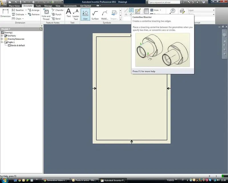
for the axis lines you have two solutions: one is the one already placed above http://www.cad3d.it/forum1/showthread.php?t=28414 which should only work if you created the tube with the automatic generator, but I don't know it, never used it! instead if you build it manually like me, you can use the command that generates an axis between two straights, to use it just click one line first then the other and generates an axis between the two straights, put an image for May clarity. in the drawing of assembly that I posted to you earlier, I inserted only the axes in the useful plan, so as to simplify things to those who read the drawing, basically at first glance you understand what plan is represented.
 

Attachments

  • Asse.webp
    Asse.webp
    70.5 KB · Views: 12
The bisector command is exactly what I needed. I hope I can thank you as you must in the future... you solved a nice problem and in a very simple way!!! :finger::finger:
 

Forum statistics

Threads
44,997
Messages
339,767
Members
4
Latest member
ibt

Members online

No members online now.
Back
Top