- Home
- Forums
- mechanical engineering
- creo parametric (ex pro/e)
- creo parametric - modeling of parts and sheet
You are using an out of date browser. It may not display this or other websites correctly.
You should upgrade or use an alternative browser.
You should upgrade or use an alternative browser.
DANI-3D
Guest
szach
Guest
yes but until here there are... of blend made so I have already made several.. the problem is when or the picture or the round are on different planes but also with different inclinations. ..as in my drawing. .
DANI-3D
Guest
Yes, I'm sorry, I've attached you the wrong file and the right one I can't find it, bear patience, I'm looking for it.
DANI-3D
Guest
szach
Guest
and how do you flatten it? Do you have an example with ray and flat wall?
Thank you.
Thank you.
DANI-3D
Guest
Hi.
I'll give you two more examples, the one that comes closer to your case is plate-ragree, but I had to remove the state slowly because it was in conflict, see if you can.
while if you like plate-agreement4, there is also the functional flattening feature.
I hope I've been helpful.
I'll give you two more examples, the one that comes closer to your case is plate-ragree, but I had to remove the state slowly because it was in conflict, see if you can.
while if you like plate-agreement4, there is also the functional flattening feature.
I hope I've been helpful.
Attachments
szach
Guest
the second opens but I do not get a circle as in the example plate fitting 3...cmq thank you very much.. This is a mess.
re_solidworks
Guest
how should the hopper be realized? I suppose in folds, but I'm not sure if you fold or print it.
szach
Guest
Dobbiamo piegare...
re_solidworks
Guest
Hi.Dobbiamo piegare...
If you do it in folds you can radiate the obstacle creating a superifice with all flat faces that approximates your hopper but that creates the real hopper that goes out in folds. do this go to inspect it and convert it into sheet metal to achieve development.
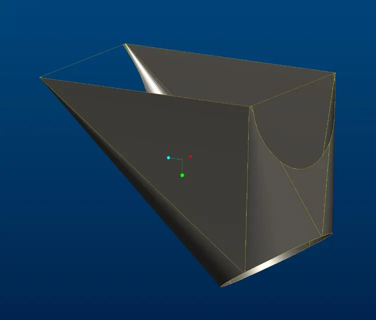
I modeled a half, but with solidworks, I'll show you, but you could do the same with proes.
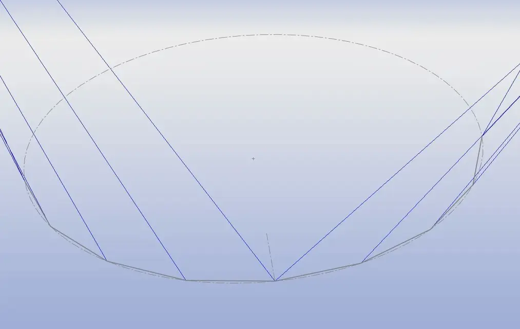
as you see, I created a lateral sketch, on which I leaned to create the sketches of the two sections to join. I didn't make it round, but it's already a polygon. I created a series of driving curves (for two points they are straight for) that educate the loft on how to combine the edges.
I then made a loft surface and performed the pipe cut,
I've inspected it and I've inserted the conversion into sheet metal.
In essence when I am in front of these situations where I do not understand how the loft sheet behaves I go to feed the cad an object that can be spread without interpretations because already composed of flat faces. in this the surfaces give you a big hand, because not having to manage the thickness the modeling is much easier; I believe that this method is applicable to all cads and is very functional.
If you want the native I can get you, at the moment I do not place it because, as already said, it is made with solidworks.
Attachments


szach
Guest
hi, I tried in every way...I joined the surfaces and I often turned it all...I converted it into sheet metal and I made the tear.I tried to flatten...but nothing...from a mistake...I also tried to create fittings keeping the same number of entities between the rectangle and polygon...but nothing! !
I don't know what to do anymore.
I don't know what to do anymore.
szach
Guest
I managed!!! thank you so much!! !
DANI-3D
Guest
Good boy.
Let us see the result.
Let us see the result.
re_solidworks
Guest
Hi, I'd like to see how you managed to close it, as soon as I get back to the office, I also try with proes.I managed!!! thank you so much!! !
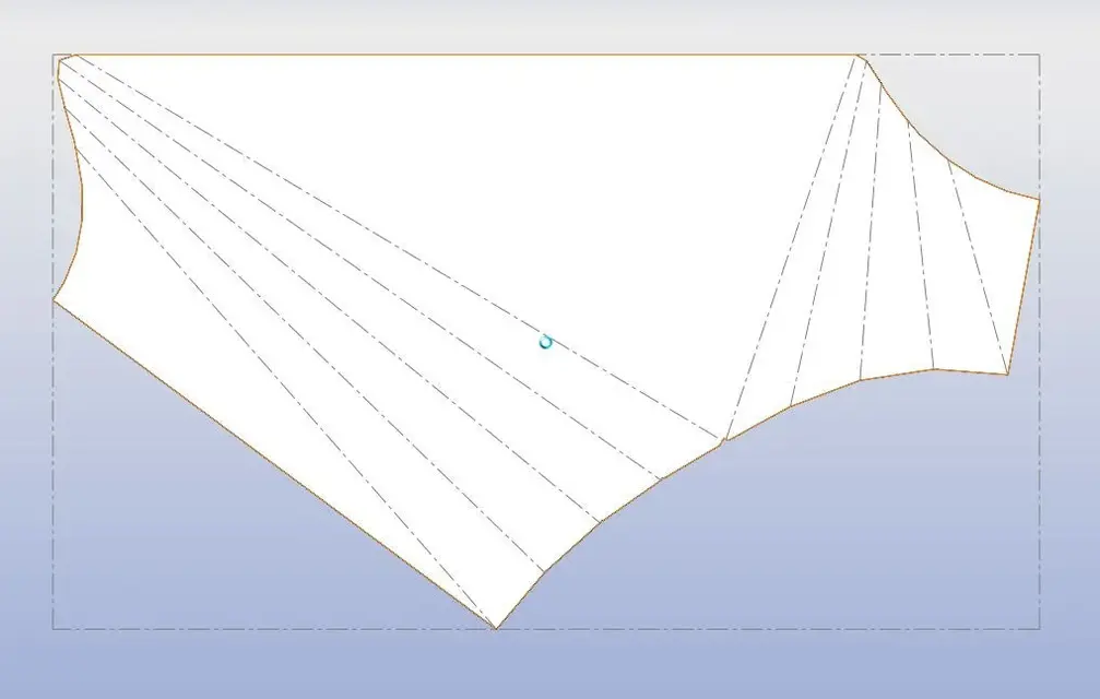
the problem that is often created when you get the sheets in this way is the discharge necessary to the fold in the points where many folds are concentrated.
in the specific case the cutting diameter of the pipe is larger than the width of the hopper and there are no exhaust problems.
when there are these failures start with macro cuts in places where the folds are concentrated and as soon as I find the one to download I go to reduce this manual discharge to the minimum allowed to solve the sheet.
with this system I made us really weird folded silhouettes and I find it a bit slender but definitely effective.
szach
Guest
blubossa
Guest
I'm sorry for my ignorance in this matter... but if I want to get the full hopper what I have to do?Here's the redevelopment... thanks again:finger:
bb
PROG_VIT
Guest
Sorry but what format is I file?Here's the redevelopment... thanks again:finger:
cm open it with solidworks?http://www.cad3d.it.cloud.seeweb.it/forum1/images/icons/icon5.gif
re_solidworks
Guest
a native of proe.Sorry but what format is I file?
cm open it with solidworks?http://www.cad3d.it.cloud.seeweb.it/forum1/images/icons/icon5.gif