• This forum is the machine-generated translation of www.cad3d.it/forum1 - the Italian design community. Several terms are not translated correctly.

function to simulate milling

  • Thread starter Thread starter Andre75
  • Start date Start date

Andre75

Guest
Good morning to all

I ask help to understand how to make the following feature on a model:

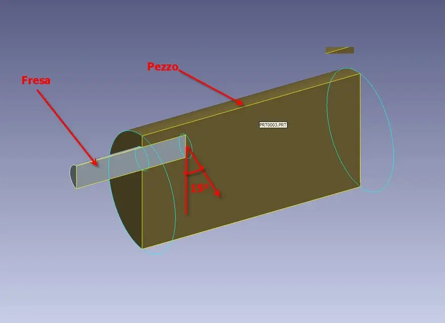
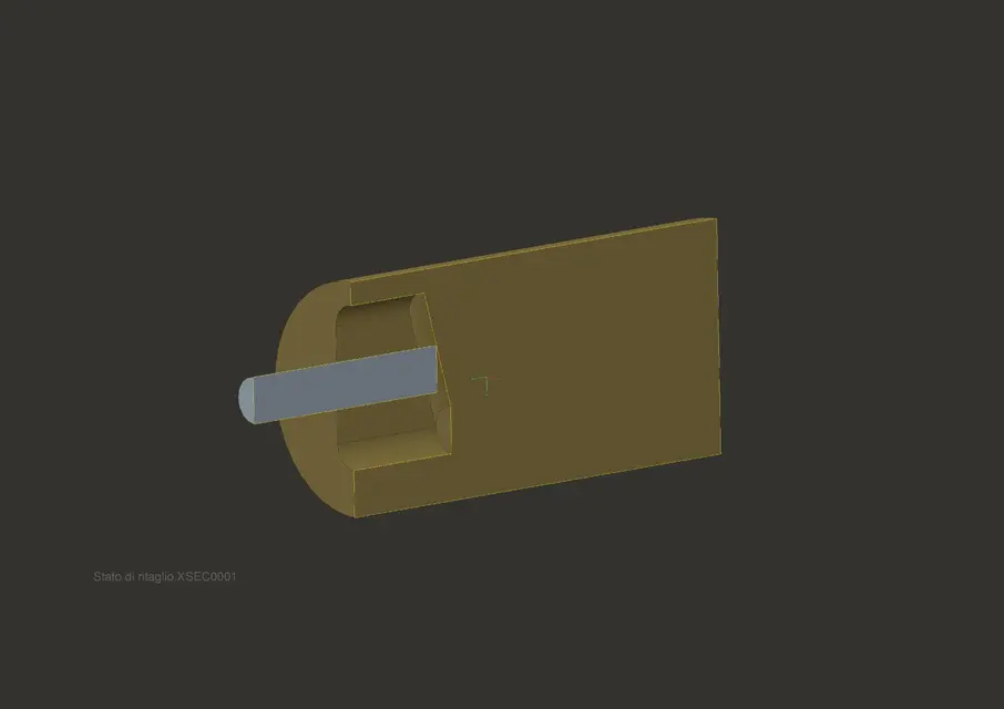
I have a candle cutter that enters 20 mm in a cylinder (see example figure).the mill then descends from them to the center of the piece with a inclination of 15 degrees.
which function should be used to represent this workmanship on the piece?

thanks to all
 

Attachments

  • esempio.webp
    esempio.webp
    24.5 KB · Views: 43
  • mdl.zip
    mdl.zip
    82.8 KB · Views: 15
in the first part you create a sketch of the path of the mill, then create a constant section cutting sweep with trajectory equal to that of the first tracked mill and with section equal to that of the circular mill profile in the plane parallel to the axis of the mill and normal on the plane containing the trajectory. the profile will be a rectangle with the side where the cutter consists of an arc of ellipse (inviluppo of the cutter in inclination movement).

of course in the entry and exit points of the cutter you have to insert two holes equal cut diameter to complete the part of the excavation.

difficult to explain, but if you understand the concept you get there alone. it would be easier to send you the model, but the graphics card does not work.. .

I hope I've been helping you anyway.

aminati
 
unfortunately the part that comes after the sketch is not very clear

Is there anyone who can put it into practice in the attached example?

Thank you.
 
provided that the processing represented in the figure would be much better to carry out it with turning and milling only in case the cylindrical part was part of a more complex detail, here is a simulation image brake paths for a processing very similar to that indicated.
 

Attachments

  • Fresatura cilindro.webp
    Fresatura cilindro.webp
    41.5 KB · Views: 40
It's a little coughier than I felt at first sight. .

I modeled entry and exit hole and the trajectory between the two points, would remain to be connected between them (those placed above the middle of the upper mill in the incoming and lower outgoing). the mill is bound so that you can drag it along the desired direction. I still believe that you could model with a single sweep of variable profile (which I never used)

I hope I've been useful to you anyway

aminati
 

Attachments

by rethinking the fastest way, even if less precise, is to create in the mechanism module the envelope of the encumbrance of the various positions of the mill in its entry movement, oblique translation and stop at the end point, then subtract this envelope to the initial piece of departure.

aminati
 
Unfortunately I can't read the files because I'm still in the wf2 version

for now thank you, I see if I can find colleagues with the wf3
 
Hello.
I did something like preparation-h. I did it with a blend even if I have to say that to respect the 15th you have to make two accounts before you model. However with the blend is simple, just do the three sections and make them have the same number of segments.
greetings
 
Here is the exact solution, always a sweep with fixed direction section that follows the trajectory and equal to the circular profile of the front of the cutter. all of course followed by the excavation done by the rest of the body hectic.

aminati

p.s. purtoppo I only have the creo version and if place in neutral you lose the features
 

Attachments

  • Fresatura.zip
    Fresatura.zip
    199.9 KB · Views: 9
  • asm0001.webp
    asm0001.webp
    70 KB · Views: 26

Forum statistics

Threads
44,997
Messages
339,767
Members
4
Latest member
ibt

Members online

No members online now.
Back
Top