• This forum is the machine-generated translation of www.cad3d.it/forum1 - the Italian design community. Several terms are not translated correctly.

glyph mechanism

  • Thread starter Thread starter Cla
  • Start date Start date

Cla

Guest
Good morning to all,

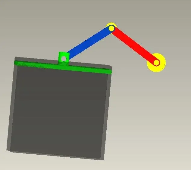
I intend to make some kind of glyph meccaniscmo. I have a part that translates and sympathizes to this c is a part that translates to a certain point corresponding to the moment when the glyph mechanism freezes (the rotation is limited), I started the set inserting the elements in this order:
  1. fixed zipper
  2. first part of the glyph
  3. cerniera mobile
  4. second part of the glyph
  5. element that translates first into a horizontal direction then into a vertical
  6. element that translates
I hope to have been clear (I see it hard) if I have to post the set I will do it immediately

Thank you.

Hi.

 
here is the immagion of the mechanism. . .

Hi.


ps: between the green part and the blue one I did not put any element to pin... to do something more quickly.. .
 

Attachments

  • glifo.webp
    glifo.webp
    10.1 KB · Views: 62
but indicate the degrees of freedom of the various components, who can turn and who translates.
for who translates let me understand in which direction.
Bye.
 
  1. the yellow zipper to the right is fixed (absolute zero hostages)
  2. the red part rotates and has as pin the fixed part indicated in point 1
  3. the second is a zipper (yellow)
  4. the blue part is bound in an extreme zipper which makes it pin and another zipper bond is on the green part
  5. the green part has as bond that of skate on the gray part
  6. the grey part translates into "horizontal"
the mechanism should take advantage of the fact that when the rotation of the red part is over the blue part continue to rotate by lowering the green part
 
mountains the red part with a pin connection compared to the first zipper
mountains the grey part with a course connection compared to a horizontal axis
the green part with a vertical course connection compared to the grey part.
the blue part with a pin connection compared to the red and another pin connection respect the green.
then you will have to go into applications > mechanism and set up the servomotors you need.
Bye.
 
in pro/e the concept of servomotors is a little different.
you need to apply a servo motor for each rotation axis.
 
I have a doubt... let's say that I have finished the axis (the one above) I have created a system like rail to give the constraint to the part in gray...from the together I can change the order of the elements on the model tree... also can I make sure that the parts during the mechanism in motion do not interfere one on the other? ?

Hello and thank you

 
you can change the order of the components, as long as the hierarchies of positioning do not conflict.
example: if b is placed on a and c is placed on b ... the order is hierarchically rigid (a>b>c) and cannot move the components into the tree.
If you want to change the hierarchy you have to redefine the positions.
if instead it is b that there are placed on a, you can indifferently have c or b after a.

to avoid interference between components you have to limit the translation or rotation movements.
in the positioning interface find the appropriate input boxes.
 
to avoid interference between components you have to limit the translation or rotation movements.
in the positioning interface find the appropriate input boxes.
and if you don't understand when something goes into interference you can always enable the option that makes you see the collisions or that blocks the mechanism as soon as it happens... in tools>assembly setting (I have proe in English). . .
 
thanks to all for the indications.

I've got a little problem... I've started doing the whole thing again, starting from this rail and then placing it in order

part grgia,
green part,
blue part,
first zipper in yellow,
part in red
...

The problem lies in the last zipper, I can't make it fixed in space... it moves me along with the mechanism... how do I say it has to stay fixed in space? ...I the neck to the red component that is bound by the pin on the first zipper...maybe wrong to give the pin bond on the first zipper and should I give it on the second...does this piece actually rotate both compared to the first and second zipper...mha? ! !

Hi.

What do you mean in space?
Should the rectangular piece move along a straight?
 
Hello, cla!
I know that at the fixed yellow hinges you have to give him the "rigid" bond at the beginning because it should be the element of land that usually stands before others!
 
Okay, but how do I put it in the red piece? first should I place the zipper randomly and then put the red piece?? Are there any other ways? ?
 
you should first insert the zipper to be fixed by taking as reference the rail, which is also fixed, so not the random position (and this you can do it with the standard couplings type "allinea") then ultimately insert the red lever with the pin constraints on the two yellow hinges.
 
the problem is that if I do with this procedure here...when I go to insert the pin bond on the first zipper I can not insert it on the second... to explain myself in practice I removed the first zipper and the red element, then I did:

1- rigid insertion of the hinge1

2- insert with pin bond of the red element

I am positioned in the background to the model tree so when I go to change definition to couple the second hinge to the red element I have nothing to refer to...to understand I don't know what position should have the hinge compared to the rail...I wanted to find the ideal position just by exploiting proes
 
Hello, cla!
I have remade your mechanism and I attach the .doc with the image I describe:
1) insert rail 1 with standard bond "defaul"
2) insert rail 2 with standard couplings "double" and "alline"
3) enter the guide 3 with "course" selecting for "axis alignment" the edge to 3, and that b of the rail, while for "rotation" select the face c of 3 (the back one) with the d of 2
4) Insert the piston 4 with "course" and "Axis alignment" select the edge and 4 with the f of 3 and for "rotation" the face g of 4 with h of 3
5) insert the 5 zipper to be fixed by placing it with standard couplings at an appropriate point that you can then change according to how it comes out all
6) insert the crank 6 with "pin" compared to the hole of 4 where in "translation" select the side faces of 6 and 4
7) insert the rod 7 with "pin" either with fixed zipper 5 or with hole 6, in "translation" select the side faces between 7 and5 ,7 and 6
8)In the end you can also insert the 8 zipper with "pin" compared to 7
so it works perfectly

Hi.
 

Attachments

  • Immagine3.webp
    Immagine3.webp
    11 KB · Views: 20
very kind... as soon as possible I try... thank you! ! !

Hi.


_

I think I have a little problem in the settings (the config)...in the file together when I insert the first component I place it myself from if without making me choose the type of bond... Do you know how to change this?? using different pcs I have some with a config some with another config.. .
 

Forum statistics

Threads
44,997
Messages
339,767
Members
4
Latest member
ibt

Members online

No members online now.
Back
Top