arzigogolo
Guest
Hello everyone!:smile:
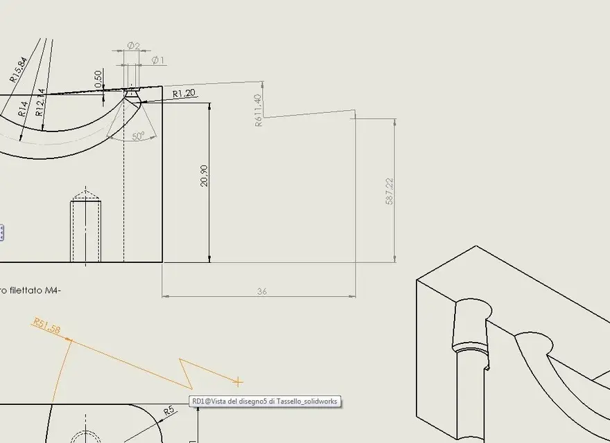
I was practicing drawing the piece of the image attached for exercise, (originally it was made with autocad 12 in 2d) and I came across this problem:
the designer, in order to overcome the lack of space on the sheet, had listed the radius of 611.40 putting a point from center of fictitious within the space of the sheet, modifying then by hand the quota text (which is very horrible to avoid as the stomachache :biggrin .
.
 I tried to see if it was possible to quote it without going the positioning quotas of the radius center out of the drawing, but I failed.
I only managed to break the ray share, as you see in the image, selecting the "reduced" option within the quota command, and came as I wanted.
I then tried to do the same with the extension lines of the two positioning quotas to let them enter the design, but it does not work with any option.
I then searched the internet, and the only thing I found was this. This is what discussion in English, where the guy seems to have found the solution with the command "spezza vista" image image image. But I tried it, but I can't break the view apart from the side of the piece, because he obviously tells me that he has no physical object to break.
and then how the hell did he break the axis of the center of the ray to get us into the sheet?
do you know if you can break with a command the quota extension lines, making them remain associative with the real value, while displaying them broken as the ray share?
I tried them all but without result. :frown:
Thank you all!
I was practicing drawing the piece of the image attached for exercise, (originally it was made with autocad 12 in 2d) and I came across this problem:
the designer, in order to overcome the lack of space on the sheet, had listed the radius of 611.40 putting a point from center of fictitious within the space of the sheet, modifying then by hand the quota text (which is very horrible to avoid as the stomachache :biggrin
.I tried to see if it was possible to quote it without going the positioning quotas of the radius center out of the drawing, but I failed.I only managed to break the ray share, as you see in the image, selecting the "reduced" option within the quota command, and came as I wanted.
I then tried to do the same with the extension lines of the two positioning quotas to let them enter the design, but it does not work with any option.
I then searched the internet, and the only thing I found was this. This is what discussion in English, where the guy seems to have found the solution with the command "spezza vista" image image image. But I tried it, but I can't break the view apart from the side of the piece, because he obviously tells me that he has no physical object to break.
and then how the hell did he break the axis of the center of the ray to get us into the sheet?
do you know if you can break with a command the quota extension lines, making them remain associative with the real value, while displaying them broken as the ray share?
I tried them all but without result. :frown:
Thank you all!
Last edited: