• This forum is the machine-generated translation of www.cad3d.it/forum1 - the Italian design community. Several terms are not translated correctly.

how to make sheet fun?

  • Thread starter Thread starter volaff
  • Start date Start date

volaff

Guest
good evening forum.
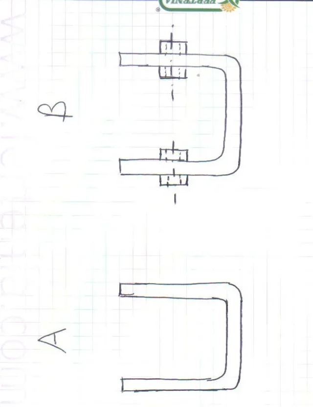
I wondered if it was possible given the sheet to make a sheet b with those two circular thicknesses on both sides and a hole passing through a forming tool? I really don't know if it's possible from both sides, from one maybe yes.
What do you think?
Thank you all.
 

Attachments

  • lastscan.webp
    lastscan.webp
    22.6 KB · Views: 9
I didn't understand your problem.. .
about how to do it with solidworks? I think it's pretty easy. design a c extrude with the sheet giving it thickener, make two holes passing and make us a revolution of the sleeves... I don't see why uncomfortable function destroyed as a rubbing
if it concerns construction in workshop
is the same thing; pieghi the sheet to c, you make us two holes (you can do them even before you do not need precise hillyness) and you store the two sleeves
 
I didn't understand your problem.. .
about how to do it with solidworks? I think it's pretty easy. design a c extrude with the sheet giving it thickener, make two holes passing and make us a revolution of the sleeves... I don't see why uncomfortable function destroyed as a rubbing
if it concerns construction in workshop
is the same thing; pieghi the sheet to c, you make us two holes (you can do them even before you do not need precise hillyness) and you store the two sleeves

ti ringrazio.
 
I actually made it easier to believe it was easier.
in sinstesi I should make on a sheet already imbuttia a kind of integrated mouthpiece passing for a hole.
if I go to create with respect to the middle floor two semiboils in the two directions I use the command "language" (to remain in the sheet) with two separate commands as the tongue command does not preview extrusion in the two directions.
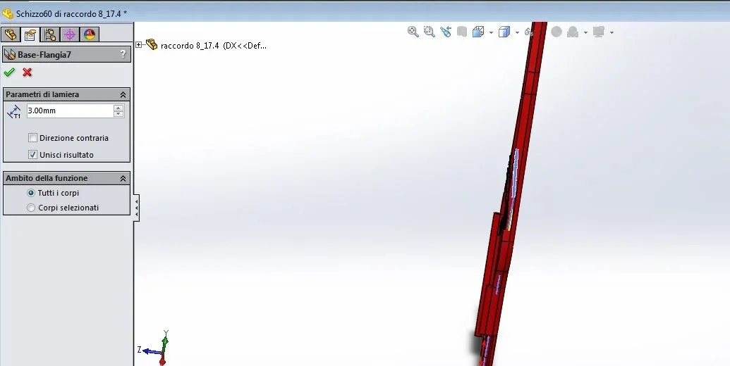
If I want to combine every semi-fold to the main body with the options in figure does not unite me the two bodies and when I go to create the mirror copy with the "technical" of the body erase that you suggested the procedure does not go well.
Are you wondering why of all this?

If I don't make bushings the software allows me to make flat mode, if I create bushings with a classic extrusion it gives me error.
since this piece is likely to be physically realized I would always prefer to ensure flattened mode.

thanks for any suggestions.
At the limit I can attach a primordial sample file so they don't arrest me! hi hi hi hi
 

Attachments

  • Immagine.webp
    Immagine.webp
    23.8 KB · Views: 18
I don't understand the problem, but you're being rude.
the two sleeves, feasible with a single function of revolution, will have to be bodies if . then when the configuration of flattening is created, if it does not automatically, you will suspend the revolution.
do not put comprehensible pictures or even files before 10# posts that we lose all the fun
 
I'll get you the file I did.
to create flattening you must insert the view in flattened mode in a drawing file; as the part is multibody to do this you have to do: select body, select the sheet in the environment part, select view in flat mode then automatically in the part the configuration with flattening is created and the two sleeves are simply hidden (but you can always suspend them if you prefer)View attachment lamiera manicotti.zip
 
I'll get you the file I did.
to create flattening you must insert the view in flattened mode in a drawing file; as the part is multibody to do this you have to do: select the body, select the sheet in the environment part, select the view in flattened mode then automatically in the part the configuration with the flattening is created and the two sleeves are simply . hidden (but you can always suspend them if you prefer)View attachment 46337
Thank you for your availability.
in the morning after doing some things I'll take a look.
Good evening and thank you again:)
 
So how did you proceed?
We good evening. Sorry if I didn't answer, I forgot honestly.
In practice I proceeded as you suggested to me that I created the two sleeves with a function of revolution and, of course, the program gave me error in flattened mode.
I suspended the function of revolution and had no problems in "appitate".

I am now having to make the table of a very similar part that, instead of a revolution, presents as a "classic" function an extruded cut (hole); If I suspect the function the flattened mode is fine, but I was wondering. . .

if I have to do the 2d and wait for the function, then in the table setting how do I take into account the hole since the function is suspended?

This is my reasoning before doing the 2d.

I can only thank you as always.
 
You didn't understand the procedure well. . .
so that the flattened mode is done correctly you don't have to do it in the part, but you have to put it in the drawing for each sheet metal body (even if you don't need the drawing); in this way solid automatically creates a configuration for each body made of sheet metal managing all the rest of the model, which can be hidden or suspended. in fact if you look with attention my file the revolution is not suspended but hidden. Maybe you had even left a result in the function of revolution

regarding the hole function did you try not to suspend it or do you always have to wrap your head before trying things?

for the development of a sheet you have to get a completely flat model, so if there are added bodies can not be done and gives you error; same thing if you have closed geometries.
a cut instead generally (but depends on how to change the geometry) does not prevent development so it should not be suspended if it is part of the sheet; Otherwise, if the cut has to be done completely by car and those who receive the sheet design should not do so (but this is a workshop and order department topic)
 
I understand I try to "put my hand" :)
with calm and cold blood.
 

Attachments

  • Immagine.webp
    Immagine.webp
    46.2 KB · Views: 5
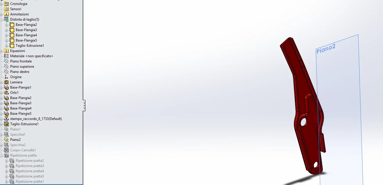
the base function - flange 1 was created by a closed profile "extruded" for sheet thickness: being closed geometry will give error then?
 
I imagined that term would create confusion, but I couldn't explain myself.
Perhaps with an example I get better, by substantiating that however it is one of the most trivial cases of a non-developability of the sheet:
take the section of a frame tube, you will see it this way, if you do not want to get it from sheet metal and then fold it you must have a cut on one of the sides, even of 0.01 mm, otherwise it gives you error. That's what I meant with a closed profile, not the sketch profile.
being closed geometry will give error then?
Why don't you ask the question yourself if you do it or not? Besides, and you should know more than well, without file you can not tell what happens in a case like this as it is important how the object was modeled
 
I imagined that term would create confusion, but I couldn't explain myself.
Perhaps with an example I get better, by substantiating that however it is one of the most trivial cases of a non-developability of the sheet:
take the section of a frame tube, you will see it this way, if you do not want to get it from sheet metal and then fold it you must have a cut on one of the sides, even of 0.01 mm, otherwise it gives you error. That's what I meant with a closed profile, not the sketch profile.


Why don't you ask the question yourself if you do it or not? Besides, and you should know more than well, without file you can not tell what happens in a case like this as it is important how the object was modeled
I'll explain.
if I go in drawing mode I appear among the views "flat recetition"; with the file under review the voice is not really there.
That's why I had the doubt.

That's all.
if I can place a similar file for obvious reasons.
 
if it is a multibody you must first select the body because it understands what must flatten; then when you enter the view you select bodies, you are sent back to the side file, click on the body affected by the confirmation and you are returned to the drawing file then you should find the interested voice
 
if it is a multibody you must first select the body because it understands what must flatten; then when you enter the view you select bodies, you are sent back to the side file, click on the body affected by the confirmation and you are returned to the drawing file then you should find the interested voice
I'm really a....one.
but this procedure should be done for every single body that forms the multibody?
selecting all the flat mode does not appear; selecting one at a time yes.


as promised here is a file part very many similar I did it with the same strategy of the original one.
I thank you and I follow the above tips.

:

Thank you very much!
 

Attachments

I'm looking at the file and that sheet can never spread that depression can't be integrated into the sheet; as you did it you can only build for molding. If this is the way you chose it is fine, but then you make a pile of useless pippes with the history of development that at most would only woven the hips.
If you want to make it as a folded sheet, I suggest another way to make a single body (excluding the depression that would be soldered later). i.e. eliminating the base flanges and making the edges without radiated parts that instead add after with the edge command.
Be careful that here solid I think is wrong in succeeding in developing, because a curve cannot bend it if not around its axis. But let's close an eye.
All right, I had a good time playing games. . .
View attachment prova2 - Copia.zip
 
I'll give him an eye tomorrow or tonight.
now to which came the spirit of making two plates that close to comb.
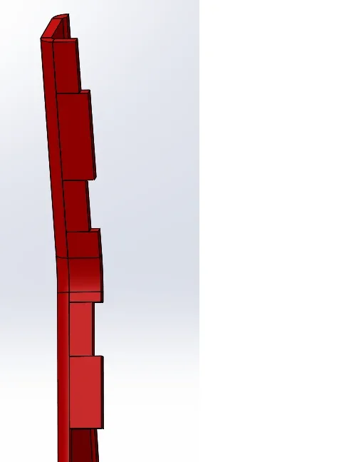
is it possible to make an extrusion flange of alternating base like that in figure without having to do one for every section of different height?

What a mess! !
 

Attachments

  • Immagine.webp
    Immagine.webp
    5.8 KB · Views: 5
The best thing is to make cuts because they're only on straight sides. Maybe together so you can take advantage of the association between the two parties.
 

Forum statistics

Threads
44,997
Messages
339,767
Members
4
Latest member
ibt

Members online

No members online now.
Back
Top