simone03031986
Guest
Hi.
I have been involved in the design and production of sports coltelleria articles and recently I am a sw user.
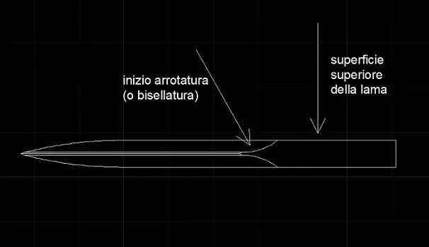
I wanted to ask which, according to you, is the best method to model the rounding and thread of a blade (and perhaps even the dorsal or counterfeit).
by means of roasting means that processing by removal of material that "finances" the blade up to the thread of the same.
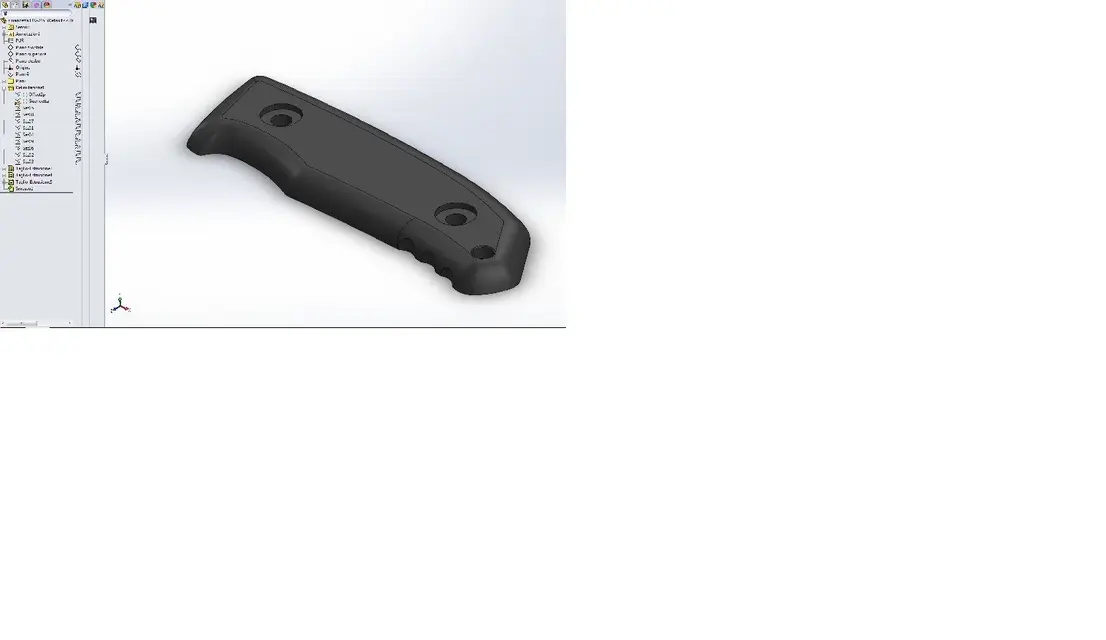
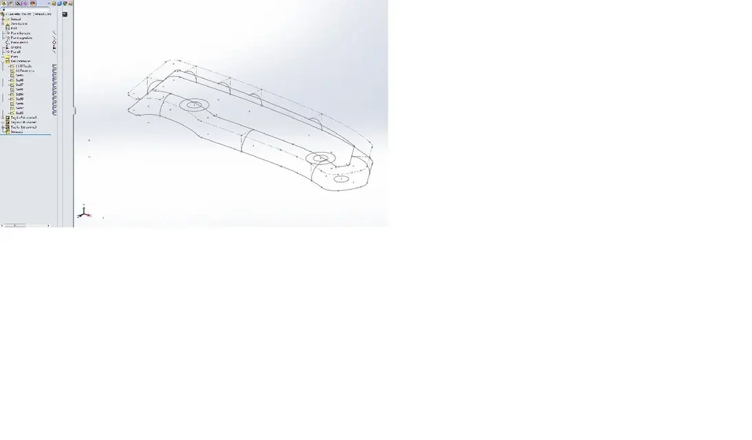
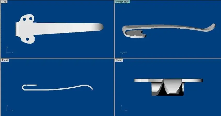
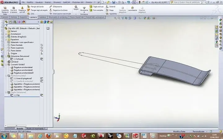
I attach an example image and a file of mine, in which, however, you can see a slip on the surface of the round.. .
Thank you, simone
I have been involved in the design and production of sports coltelleria articles and recently I am a sw user.
I wanted to ask which, according to you, is the best method to model the rounding and thread of a blade (and perhaps even the dorsal or counterfeit).
by means of roasting means that processing by removal of material that "finances" the blade up to the thread of the same.
I attach an example image and a file of mine, in which, however, you can see a slip on the surface of the round.. .
Thank you, simone
")