• This forum is the machine-generated translation of www.cad3d.it/forum1 - the Italian design community. Several terms are not translated correctly.

i would like if possible a small help and any corrections

lizardluc

Guest
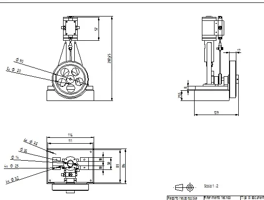
Hi, I should finish a project for an examination by making tables, I wanted to know if someone very kindly could give him an eye and tell me if they are correct from the mechanical design viewpoint.
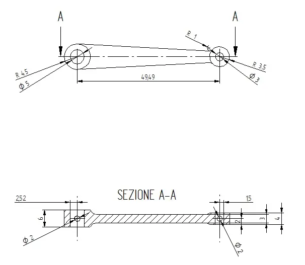
in the view of the set were necessary only the quotas of encumbrance, while in the quotation of the biella are uncertain about the fact that the section should be dissected or not and if it was necessary a tear to show that the transversal holes were passing only half!
thank you so much in advance to anyone who will give me time!! !Cattura.webpCattura2.webp
 
Hi, I should finish a project for an examination by making tables, I wanted to know if someone very kindly could give him an eye and tell me if they are correct from the mechanical design viewpoint.
in the view of the set were necessary only the quotas of encumbrance, while in the quotation of the biella are uncertain about the fact that the section should be dissected or not and if it was necessary a tear to show that the transversal holes were passing only half!
thank you so much in advance to anyone who will give me time!! !View attachment 36442View attachment 36443
- in the view you've listed rays when you should quote diameters (4,5 and 3.5)
Is the whole of the biella really 49,49?
- in the section the odds 2,52 and 1,5 do not understand well what they are, if they are the "roar" of the hole you should put a quota of the diameter with the symbol of the diameter.
- in the main view show at least the cross holes with hidden lines
 
As far as the total is concerned, you say that only the bulk quotas are needed.
However, you have also listed several diameters (view in the plant) without indicating their position.
In other views, apart from the height (even here the ,5 cannot be avoided at least not showing it), there are odds that seem randomly placed. What do I need to indicate that the pulley has 5 holes diameter 20 ?

think about what information you need to communicate with the drawing, usually in a total serve: dimensions, ground connections and interfaces with users. if it is a constructive then then serve the assembly quotas components and a list parts with ballpointing.

I guess you use the student version so I can't open your files.

Hi.
 
Yes, in the biella put an interrupted section or hidden edges to show how deep the hole is.

In addition to what has said be_on_edge, very just, I would add that you could put a little better axes, there is no bevel, not a tolerance, do not repeat the quotas (a diameter in a view and a case of radius in that below is very wrong).

In the axieme, if you tell me the fixing holes, give me also the interasses between them.
do not fear to put axes, with they cost a lot:
- main axes of the axieme
- symmetry axes,
- axis of the pieces of revolution
- interassisted

quotas in assemblies:
- Of encumbrance,
- external coupling
- if there are adjustment and position ("57" is running? )

- is it essential to know that the pulley has 5 holes d20?
 
I add that then from the design of the axieme you should understand what this machine does.

What's the point?
 
geometric and dimensional tolerances did not put them as in the document is already indicated iso 2768-mk and iso 8015.
Am I wrong? ?
 
geometric and dimensional tolerances did not put them as in the document is already indicated iso 2768-mk and iso 8015.
Am I wrong? ?
everything is related according to the purpose (function) and the technology available (production cycle, quantity, lot, i.e. necessary accuracy and final cost of the piece):
dimensional and geometric tolerances, and roughness must be as wide as possible within the limit of not compromising the operation and allowing the assembly, because so the piece costs you less (precision and accuracy costs).
"maximum efficiency and minimal effort" means that someone has studied us over and nothing is left to chance.

in the vademecum baldassini p. l15-l17 it is explained that a workshop with average precision degree obtains medium tolerances as from general indications.
the reference to the legislation here written is: uni en 22768/1 and uni en 22768/2 (check your reference, since it does not coincide)
from which the example uni en 22768/2 - mk, grade of finishing and medium tolerance ("k"), applied to linear and angular dimensional and geometric tolerances ("m")

that doesn't have much to do with the speech to get just what you need, that I did on it.

Have you ever heard of tolerances in relation to 'play', 'uncertain', 'con interference' couplings?

Do you know what a hole in tolerance h7 is?
 
I know very well what a hole to tolerance h7 dear friend!! !
I solved all the problems and delivered the project that together with that created with rhinoceros I took 28..!!!
 

Forum statistics

Threads
44,997
Messages
339,767
Members
4
Latest member
ibt

Members online

No members online now.
Back
Top