Joel
Guest
Bye to all,
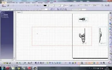
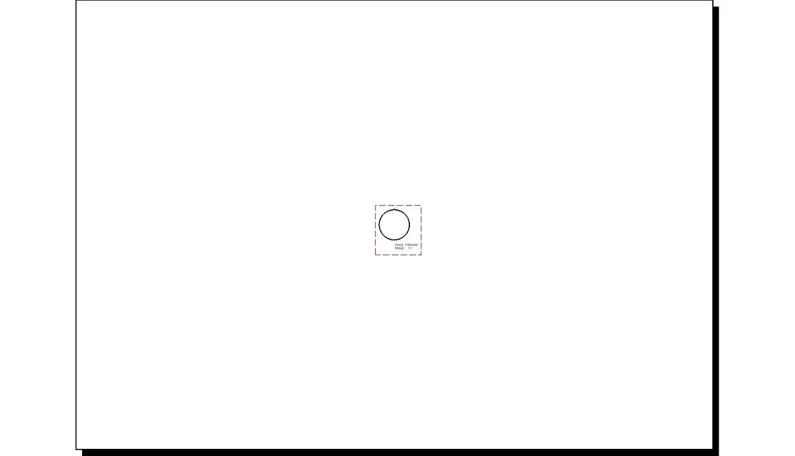
I would have a doubt about something that happens to me when I make the drawing, until a long time ago I did not give you importance, but now I would like to understand how it works: in the drawing that I attach there is the frame of the drawing that as you see is very big, and sometimes happens that it is (as in another design I have done) that has oversized !!!, as I repeat until a short time ago I did not pay attention, but now I want to understand .... Would I like to know if there is a way to change the frame size?? .
Thanks for the answer.
Joel