• This forum is the machine-generated translation of www.cad3d.it/forum1 - the Italian design community. Several terms are not translated correctly.

laser cutting and sheet bending: recessed screws?

  • Thread starter Thread starter cicciounico
  • Start date Start date

cicciounico

Guest
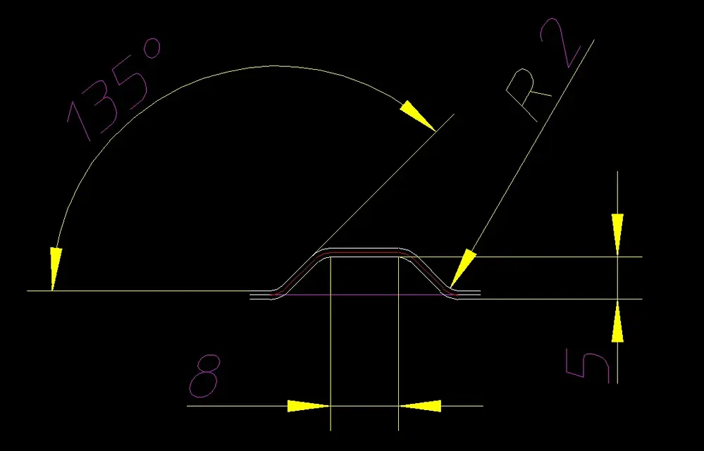
Hi, in my 1mm thick 304 steel box, I would like to make recesses for "hiding" the fixing m3 screws.
I do not know the technical name but they would be made about this:
Iing2.jpg

the question is: with the cad (solid) I can make it high until I want but what are the limits imposed by the thickness and the material?
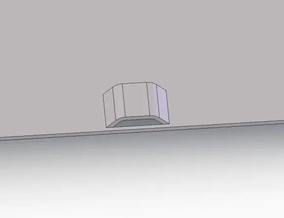
If I get up by 1mm how thin it gets? otherwise it is better to cut the tab on 3 sides instead of only on 2 in this way:
Iing1.jpg

advice? formulas?
Thank you.
 

Attachments

  • ling2.webp
    ling2.webp
    4.6 KB · Views: 32
  • ling1.webp
    ling1.webp
    12.9 KB · Views: 37
Last edited by a moderator:
Hello, my name is paolo gagliardi
I am a tool designer for sheet metal processing.
I read what you wrote, and I can tell you that you have to check if the type of sheet you want to work can undergo the stretch you ask.
In the example I attached, the development of the sheet is 25.85 mm (red line) while the sheet in the initial condition is about 22.15 mm (line magenta).
Thus the % extension is 16.7 %.
for stainless steel sheet 304 sp. 0.5-1.5 mm the % extension that you can consider in safety conditions is about 35%, so the processing is feasible.

I hope I've been helpful

Hi.
Palo
 

Attachments

  • Cattura.webp
    Cattura.webp
    18.5 KB · Views: 31
Thank you very much for the answer.
Sorry ignorance: for the calculation therefore I can consider an elongated hypotenuse of 35% i.e. if fold 8 mm to realize the oblique sides of the isoscele trapeze, can I consider 8x1.35=10.8 mm of oblique side, hypotenusa = 10.8mm?
Can you go as an account?
Thanks again.
 
exactly you can take this consideration, only that the hypotenuse should be taken on the neutral line of the sheet. for simplicity you can consider it on the half-car.
However as an order of ideas never use the maximum length to avoid any breakage due to the poor quality of the sheet.
I would stay around 25%
do not hesitate to contact me for any other doubts.
consider also the width of the cut tab, as the sheet in the central area, the straight one, tends to tighten.

Hi.
Palo
 
resumed this discussion, it would be interesting to calculate force through punch to cut and pray that pocket.

in my calculation hypotheses that I have always kept good, I calculated:
- horizontal cut length (central part) to be drawn as straight punch and then input cutting force fi
- classic shear force component for the two sides fc

I have always added the two forces to determine the maximum strength, but I have never gone to see if the bending force, which I have never calculated, is really lower than that of straight cutting going so in shadow.

In reality the punch arrives on the material and must affect it by winning fi, then as the race progresses, fi=0 and begins to grow fc and at the same time a bending force fp.

fp is a force deriving from the bending of the initial beam stuck to the extremes, forcing to a traction on the section.
I would have such a situation... or even better between p and p I would have a uniformly distributed load... and maybe I wouldn't have the supports but two frames.
screenshot_20191229_092148-jpg.55615
Do you have any ideas about this?
 

Forum statistics

Threads
44,997
Messages
339,767
Members
4
Latest member
ibt

Members online

No members online now.
Back
Top