mir
Guest
Hi.
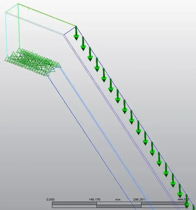
I often encounter (in the project draft phase) in considerable oversizes and observe that a 2d analysis (classical analysis to be able to do with a paper leaflet) is very different from an analysis to the fem ... do you also observe it?
I often encounter (in the project draft phase) in considerable oversizes and observe that a 2d analysis (classical analysis to be able to do with a paper leaflet) is very different from an analysis to the fem ... do you also observe it?