• This forum is the machine-generated translation of www.cad3d.it/forum1 - the Italian design community. Several terms are not translated correctly.

make an aluminium sleeve, by means of shell casting (with catia v5).

  • Thread starter Thread starter Roxkill
  • Start date Start date

Roxkill

Guest
I wanted to put this "exercise" in the first place in order to make it clear to those who consult this debate: what is the difference between a designer and a designer, as you go from designer to designer (at least in this field) and perhaps giving advice to those who like so many are convinced that by doing courses in consulting agencies (for more than 2,000 euros in a week) they can learn how to deal with "jobs of the genre"! !

the test consists of:

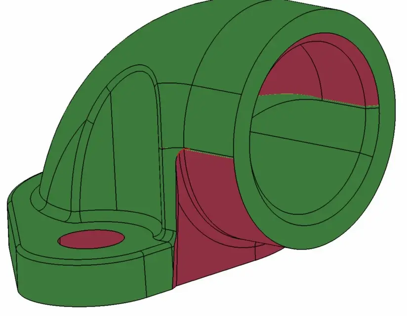
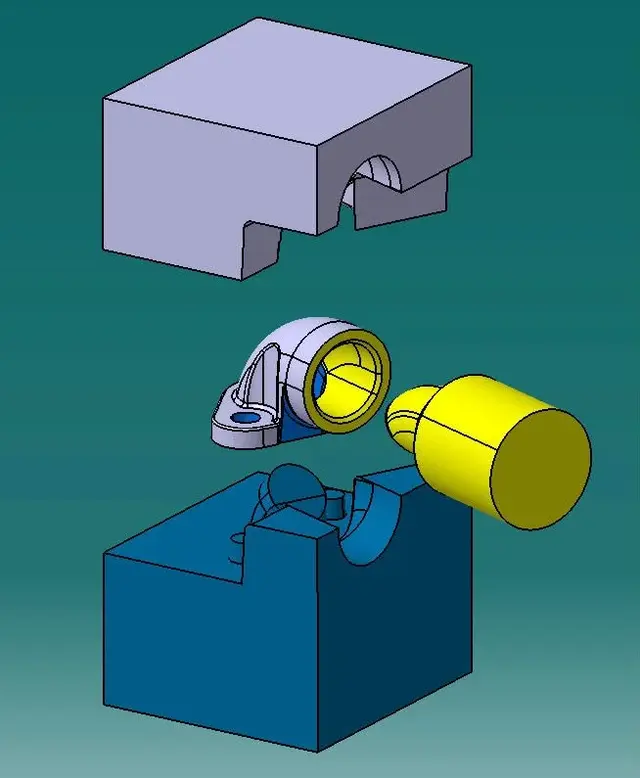
• draw the sleeve that connects the bracket (1 of figure) with the rubber tube (2 of figure) . the sleeve serves for passage water from the bracket to the rubber tube.

the sleeve is made of aluminium, by means of shell casting.
as starting data is given the interface of the bracket, with its seal the two screws to the fixing of the component, and the black tube that defines the water output from the sleeve.
as data for the design you must take into account the general sform of 1 / 1,5°, supermetal of 1mm minimum rays of 1mm.

the result we want to achieve, is a 3d model including sforms, pattern division line, ray, and that has accessibility to the screws.

ps:
you wanted to achieve at least without thinking about fusion, overmetal etc... which are the difference and from where to start, "especially" for those who are loaded with conversions of drawings from 2d to 3d, but there has never been the problem of creating something, as in this case...

Thank you all.

Good evening.
 

Attachments

Hei rox....
I tried to open files with v5 r20
But it gives me an error message... .
is it possible to open the files in the folder parts ?.
Hi.
to the
 
Hey, rox, how are you? Are you okay?

Your discussion is interesting. We hope to raise the interest of many.
 
Hey, rox, how are you? Are you okay?

Your discussion is interesting. We hope to raise the interest of many.
Hi.
Thank you, it's okay for now, even if the English some days is accessible and some others a little less!!!! (but it's the beginning... Then it will be worse!

I hope that you raise at least someone's interest, I hope I've been clear in why I put this post, it's not just the "we solve the exercise", but we try to make you understand "or remember :mixed: " (in some cases) what you currently know and how to get to certain levels.... although I know that it is not a thing to sum up in a few lines!!!

hello "Children", when are you going to make a holiday in London??? ? ?
you know in this period is so cold: eek: how beautiful.. .

good evening to all (with an hour less than fusary)!! :biggrin:
 
to stimulate discussion this is my solution

Hello everyone
That sounds great.
personally I would have made the screw hole sform on the contrary, that is the big diameter from the part of "access" screw.

attention also to where the closing plan is really located (it is about 2 tenths lower than the chord that "draws up" the plan.
but also this is just a nuance.
 

Attachments

  • chiusura.webp
    chiusura.webp
    41.3 KB · Views: 52
Hei rox....
I tried to open files with v5 r20
But it gives me an error message... .
is it possible to open the files in the folder parts ?.
Hi.
to the
Hello,
I have the file with the r21, I think it could make you trouble in opening! ! !
 
to stimulate discussion this is my solution

Hello everyone
Hi.
First of all thank you for your intervention, which I underline as jari, I liked (in terms of realization), I ask you now, if you have time and if you want, maybe to give an idea to those die casting has never done it, or it is at first, how to get into this sector.... tips advice or what you think is best for those who pass or "wan" switch from transforming 2d into 3d to you.

Thank you,
I take advantage of it by greeting everyone....

 
Meanwhile I give my thought:
disassembly and disassembly, everything that is zama, aluminum etc...
disassemble anything and understand how the mold was divided
and what measures have been applied by the designer.
every sign on the piece has a reason, we have to understand them all.
 
Hi.
First of all thank you for your intervention, which I underline as jari, I liked (in terms of realization), I ask you now, if you have time and if you want, maybe to give an idea to those die casting has never done it, or it is at first, how to get into this sector.... tips advice or what you think is best for those who pass or "wan" switch from transforming 2d into 3d to you.
Hello roxkill

hello, unfortunately I am not experienced neither of "pressofusion" nor of "casting in shell".
I can only say how I dealt with the model.

normally objects created with molding technology, I address them creating the object, thinking the constructive features of the mold instead of thinking the object for its purpose.
this always after a preliminary realization of the guiding elements of the object, example; support bracket, fitting surfaces etc.

I expected more observations like that of jari, which demonstrates to work in the field, and I take advantage of asking him to motivate his observation.

greetings
 

Attachments

  • stampo.webp
    stampo.webp
    29 KB · Views: 78
Last edited by a moderator:
Hello roxkill

hello, unfortunately I am not experienced neither of "pressofusion" nor of "casting in shell".
I can only say how I dealt with the model.

normally objects created with molding technology, I address them creating the object, thinking the constructive features of the mold instead of thinking the object for its purpose.
this always after a preliminary realization of the guiding elements of the object, example; support bracket, fitting surfaces etc.

I expected more observations like that of jari, which demonstrates to work in the field, and I take advantage of asking him to motivate his observation.

greetings
thanks anyway for your participation. . .
 
Well the widest hole on the part of "access" screws, serves to facilitate the insertion of the screw (especially in uncomfortable areas).
while for the closing floor speech, it is this: if you notice well in the image that I had attached (after opening the 3d of ferretium) the connection highlighted in red is located just above the delimitation of the two zones (green and red).
should instead start the two zones exactly at the end of the two (matrix and sting division).
 
to stimulate discussion this is my solution

Hello everyone
Hi.
very interesting, I should make it in nx to practice... how do I see the chronicle of the features used to use it as a tutorial? ?
Thank you in advance.
 

Forum statistics

Threads
44,997
Messages
339,767
Members
4
Latest member
ibt

Members online

No members online now.
Back
Top