• This forum is the machine-generated translation of www.cad3d.it/forum1 - the Italian design community. Several terms are not translated correctly.

maximum load calculation

  • Thread starter Thread starter ziotoy
  • Start date Start date

ziotoy

Guest
I am asking you the following question.
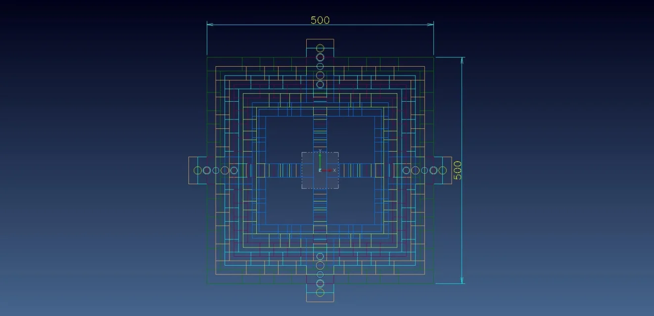
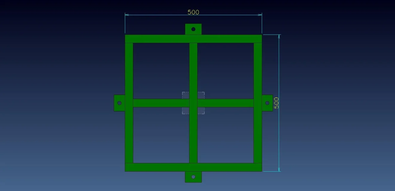
I have a tower consisting of 6 electro-welded blocks, started with 4 screws m16 each other as well as from enclosed step.
the question is this: What is the maximum weight expressed in kg or tons that can support the tower??
thank you in advance to those who will answer.
Say hi.
Uncle
 

Attachments

the rules are vast and assume knowledge about it.
I have no knowledge of structural calculations.
Therefore if someone has 5min. to open the step file with software for such calculations I would be grateful.
Say hi.
Uncle
 
put an image instead of a step. Maybe everyone sees it
I can't see the step now, so...
 
idem... on the phone no step. put an image.
However if you want to know what a structure has to do it a competent...you know if it doesn't hold people die.... civil and criminal responsibility. we poetry also tell you that it holds 5....50....50000 elephants.
 
without seeing the step I would say that the traction tower holds the load capacity of the 4 m16 screws of which you do not tell us the resistance class, so for me they are in nylon and keep less than the weight of each block of the tower.
resistance class. . You're not telling us anything.

compression... if it's a traliccio, it's gonna hold the pipes of the traliccio... it's gonna be dismantling the forces... the knots... balance... and then the tip load will be there or not?
I think it's gonna be a couple of hours to make the deal by hand. a fem... much less but then it should be interpreted.
 
Okay, I'm sorry.
I'll tell you what to do. we have to raise a couple of centimeters a mechanical press of about 120t to parade the thicknesses now existing under the 4 "foot" to replace them with shock absorbers. We will raise the press first on one side (so in theory about 60t) with 2 towers on which it will be placed for each one a pneumatic cylinder with a diameter of 180mm. the pimples are common vines of the trade m16 and they only serve to hold the blocks on each other. the two towers will be placed on the ground under the press in the immediate vicinity of the two "foot" and from there the pneumatic cylinders should raise the press. each tower consists of 6 blocks (for convenience of transport and weight) of electro-welded fe with two central cross ribs (cylinder working area) of the thickness of 30mm. Moreover always for problems of handling and weight the tower is tapered. starts from the bottom with a xy encumbrance of 500x500 up to 1800mm total height with xy encumbrance of 300x300. I hope I've been clearer this time.
Thank you all.
 

Attachments

  • TORRE_FRONT.webp
    TORRE_FRONT.webp
    16.6 KB · Views: 7
  • TORRE_ISO.webp
    TORRE_ISO.webp
    46.6 KB · Views: 11
  • TORRE_PIANTA.webp
    TORRE_PIANTA.webp
    54.2 KB · Views: 5
  • TORRE-BASE_PIANTA.webp
    TORRE-BASE_PIANTA.webp
    14.3 KB · Views: 5
therefore the screws serve only to center and to keep them fixed.
They don't work.
you need to dimension the structure so that it resists.
make a compression calculation on the tower.
Tell you how much it resists is a little too much though, you need to make some good buns! It's 60t.
Okay?
 
If it is true that the cylinder is tire with 180 mm aleage.... to 6 bar raises about 1500kg... you will never rise or 120. .
60...30ton.
I hope it is a high-pressure enerpac oil cylinder for adequate lifting interventions....both not to rub everything, or not to get hurt.
raft the composite towers to mount the pencil that raises half a press.... now you understand what you have to do.

the structure works as imagined.
the minimum section is that which must be verified, therefore if your stools are milled above and below, then lean well, they will have a contact area given by the smaller cross added by the square frame. We're talking about the top element.
the heavy force on this area is 60ton/2 if the press is lifted on one side with two hammers. 30ton = 300000n.
you will get a force/area compression sigma. This value must be less than rs/6, where rs is the electro-welded steel yield limit of the stools and 6 a safety coefficient much greater than usual 1.5 due to the dangerous application.
if this is true your structure resists compression.
each stool will then have as compression force the weight of the row of upper stools to be added to the weight force of the press.
This is the bill of the servant....
then you can make different considerations and insights, including a fem.
However it is badly designed the foundation of the press because normally on the floor there are niches to put the compact cylinders for lifting and not in the hole with extensions... .

If stools are really like photos are downloaded and for this reason you have to see how much effective compression resistant section is. you have done so much to do everything light and downloaded but you have removed meat to the soul that resists compression.
I think it was enough for a 300x300x1800mm in s235jr and it cost much less....3mpa compression that is nothing compared to rs/6=200/6=33mpa.
 
chapeau to mechanicsmg. You know exactly what we have to do. the stools will be milled to have a perfect 3 coupling and good x ground support in the hole. the cylinder is clearly suitable for the type of work. For the record, it's not like we've done the tricks to "find" the stools. It is that we do not have room for manoeuvre therefore we must fall and mount to "arm" all in the hole under the press and given the size and weight I do not know if I explain. Clearly it would have been easier and cheaper to take a full block of the size you mentioned. I don't know what to tell you. I'll design sheet molds so you're probably completely right. thanks cmq for the help. Say hi. Uncle
 

Forum statistics

Threads
44,997
Messages
339,767
Members
4
Latest member
ibt

Members online

No members online now.
Back
Top