keccossj4
Guest
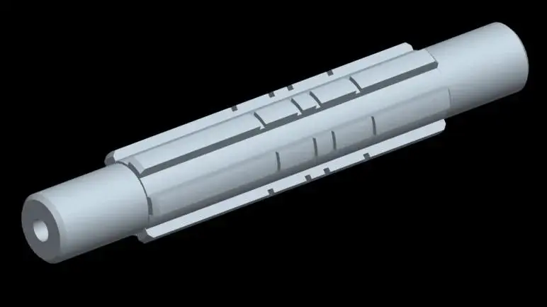
Hello everyone, I am new in the use of ansys and I am carrying out an exercise say end to itself on static analysis of a tree of a mechanical change for a motorcycle
The problem is that I got stuck on the definition of forces and vincos at stake.
I imported the geometry file from the pro/e exporting to .sat (agis)...export works because I tried it on an altyro piece
I should bind the shaft with two bearings (a hinge and a cart) placed in the lower diameter zone and two forces (which derive from the intrusion of the dentate wheels)...the forces are not on the axis of the shaft but at distance (26mm and 19mm) therefore generate as well as cutting also torque moment on a portion of tree...how do I define these forces and constraints.
thank you... if someone helps me really save my life