Gearscrew8
Guest
Bye to all,
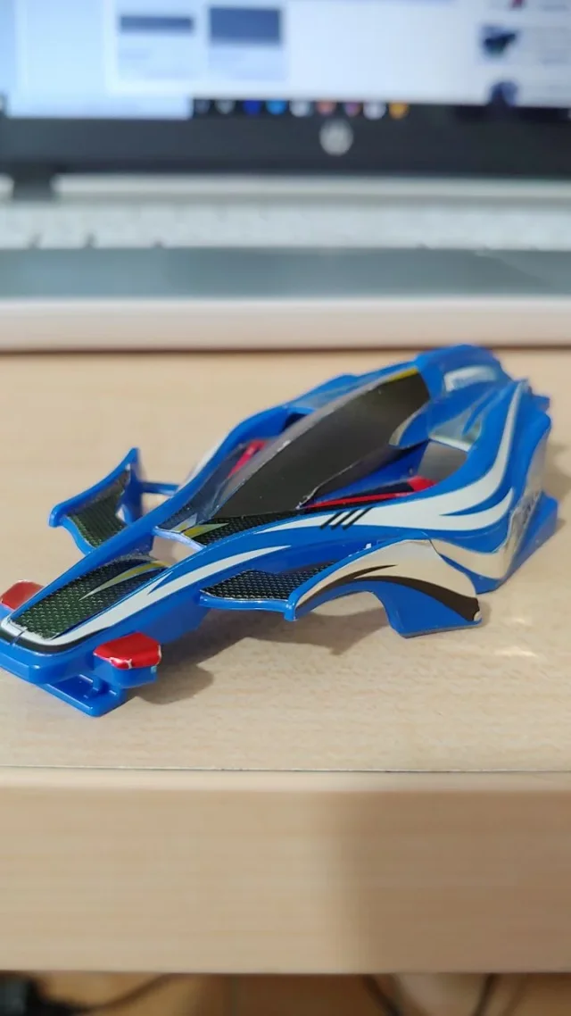
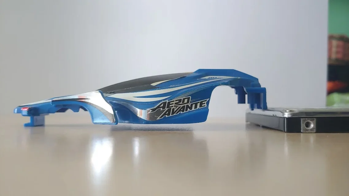
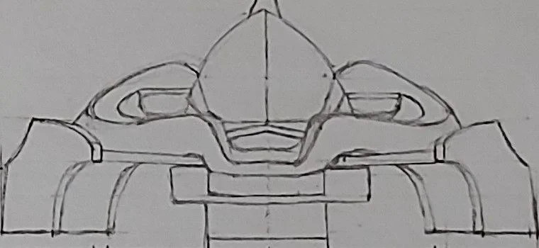
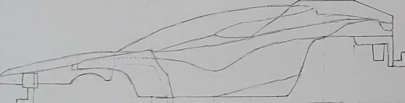
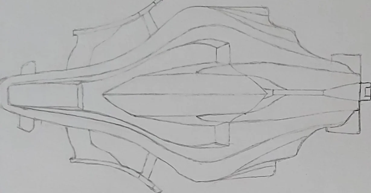
for cad examination at university I have to build an object on rhinoceros 5 and I chose the body of my mini4wd. I started modeling it through 1/2-track sweep, but I don't think I took the right path. I'm having trouble: with the front side of the muzzle (agreement 3 edges that does not close the edge) I fought us day and night but I did not find a solution; with the back, instead, I would need advice on how to shape it that I can't figure out how to do it.
Could someone give me advice?
Thank you in advance!


")