arzigogolo
Guest
Hello, everyone!
I recently came across a problem with which I had already confronted myself in the past and that I had solved with an explanation I had found looking on the net.
the problem is right here: I don't remember where I saw this explanation anymore.
I would like to find it because, for me, it was something I would never have managed to do without that explanation, in fact it was a fairly complex procedure that articulated in different passages.
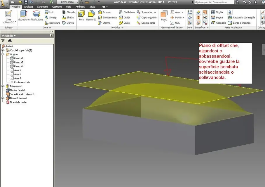
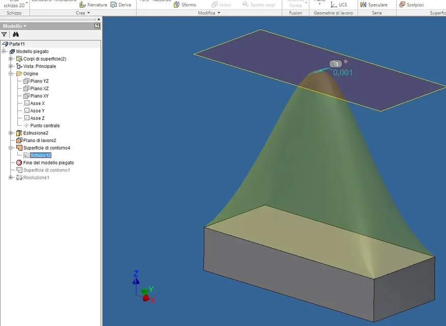
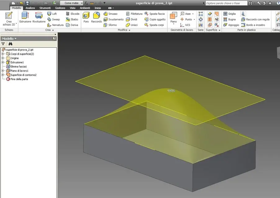
basically the tutorial, explained in passages with screenshots, referred to the possibility of "solving" a surface but keeping it connected to the basic contour (as if I had a cube and tried to "bomb" a face inserting hypothetically a ball from the inside of the cube below one of the faces).
explaining to me with another example, it is as if I had a large rectangular paper sheet or with any other shape, fixed on the ground, and I tried to lift it from below with a ball or a ball.
of course the sheet should create a central hump corresponding to the shape of the ball, but without separating itself from its edges that represent the shape. It should therefore be elastic, of course, in order to deform.
here all this explanation was translated into inventor commands and, coarsely, I can try to reproduce it until I remember, in the hope that some of you who will read this post, can help me track that site where I saw the demonstration.
the procedure, in order to obtain a surface bombed by a flat surface was described as:
1 - create a sketch with any polygonal shape, (quadrate, rectangle, circle, etc.).
2 - extrude it as solid.
3 - eliminate the upper face with the "elimina face" command.
4 - create a surface corresponding to the eliminated face presumably with the command "contour surface"
5 - to create a floor resting on the newly created replacement surface and, through a series of few other steps that I have not clear, it was possible to "unite" the surface replaced with the plan created on it.
done this, "offsetting" the plan upwards, the surface would follow it by creating the bombing, but sending "attached" to the edges.
Maybe some of you will have done it already and maybe you can explain the procedure without needing to find the link I look for.
I just hope I've explained myself quite clearly to make understand what I'm looking for and that you can help me find that link because it was a nice system explained very well.
the site was very similar to this http://www.kwikmcad.com/iclips/avi.aspxand in fact initially I thought it was this and instead it was not so.
Among other things, on the page I linked, there is the very interesting procedure to create a half-car axis in the center of an asola.
Thank you so far for your help!:smile:
Thank you.
Light
p.s.
I attach an image as far as I can get there.
I recently came across a problem with which I had already confronted myself in the past and that I had solved with an explanation I had found looking on the net.
the problem is right here: I don't remember where I saw this explanation anymore.
I would like to find it because, for me, it was something I would never have managed to do without that explanation, in fact it was a fairly complex procedure that articulated in different passages.
basically the tutorial, explained in passages with screenshots, referred to the possibility of "solving" a surface but keeping it connected to the basic contour (as if I had a cube and tried to "bomb" a face inserting hypothetically a ball from the inside of the cube below one of the faces).
explaining to me with another example, it is as if I had a large rectangular paper sheet or with any other shape, fixed on the ground, and I tried to lift it from below with a ball or a ball.
of course the sheet should create a central hump corresponding to the shape of the ball, but without separating itself from its edges that represent the shape. It should therefore be elastic, of course, in order to deform.
here all this explanation was translated into inventor commands and, coarsely, I can try to reproduce it until I remember, in the hope that some of you who will read this post, can help me track that site where I saw the demonstration.
the procedure, in order to obtain a surface bombed by a flat surface was described as:
1 - create a sketch with any polygonal shape, (quadrate, rectangle, circle, etc.).
2 - extrude it as solid.
3 - eliminate the upper face with the "elimina face" command.
4 - create a surface corresponding to the eliminated face presumably with the command "contour surface"
5 - to create a floor resting on the newly created replacement surface and, through a series of few other steps that I have not clear, it was possible to "unite" the surface replaced with the plan created on it.
done this, "offsetting" the plan upwards, the surface would follow it by creating the bombing, but sending "attached" to the edges.
Maybe some of you will have done it already and maybe you can explain the procedure without needing to find the link I look for.
I just hope I've explained myself quite clearly to make understand what I'm looking for and that you can help me find that link because it was a nice system explained very well.
the site was very similar to this http://www.kwikmcad.com/iclips/avi.aspxand in fact initially I thought it was this and instead it was not so.
Among other things, on the page I linked, there is the very interesting procedure to create a half-car axis in the center of an asola.
Thank you so far for your help!:smile:
Thank you.
Light
p.s.
I attach an image as far as I can get there.

 . the surface of the canvas will be deformed assuming the spherical shape of the sphere while remaining attached to the edges of the frame.