• This forum is the machine-generated translation of www.cad3d.it/forum1 - the Italian design community. Several terms are not translated correctly.

modeling piece

  • Thread starter Thread starter volaff
  • Start date Start date

volaff

Guest
Hello, everyone.
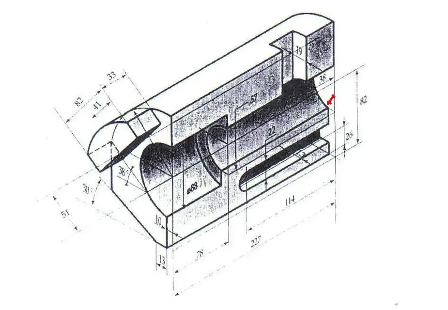
I should make this piece to solidworks and I was wondering what the simplest and most suitable strategy was.
I had thought of two possibilities:
1.realize a 180 ° revolution future and then carry out various excavations
2.make a c profile and then extrude it.

in this second case how could I do since the "vertical" parts of the c are not aligned but are 10 mm moon on the other? ?

Thank you all.
Perhaps I would first model it is true but it is true that it is always starting with clear ideas:-)

Good evening to all!

ps: I just realized that with the extrusion just create the "full" profile and then dig.
Damn headache!! !
 

Attachments

  • lastscan.webp
    lastscan.webp
    67.3 KB · Views: 93
I would say that that design is a section of a whole tube, it could be even so but with little sense.

methods are multiple. the most sensible one if you have to realize it as it is seen, you do the extrusion of the shape to c, extruded cut or revolution for the inside, cut for the rectangular tab, cut extruded for the quarry with the sketch in the shape of asola
 
Thank you very much.
I'll try.
Now I have to quit the pc otherwise my eyes commit suicide! :-)
 
I would say that that design is a section of a whole tube, it could be even so but with little sense.
I doubt it's a whole tube.
How would you realize in a tube the 112 long asola and that other upper rectangular quarry?
Whereas it is a mesozoic design :smile: , I don't think they had dip electroerosion to do that.
 
I tried to shape the silhouette to c however, in fact, it does not make too much sense to make the hole of the c, excavation that will go fatt after.
but that share of 38° what does it refer to?? ?
Thank you all!
 
I tried to shape the silhouette to c however, in fact, it does not make too much sense to make the hole of the c, excavation that will go fatt after.
but that share of 38° what does it refer to?? ?
Thank you all!
is the corner of the dentello wall compared to the horizontal
 
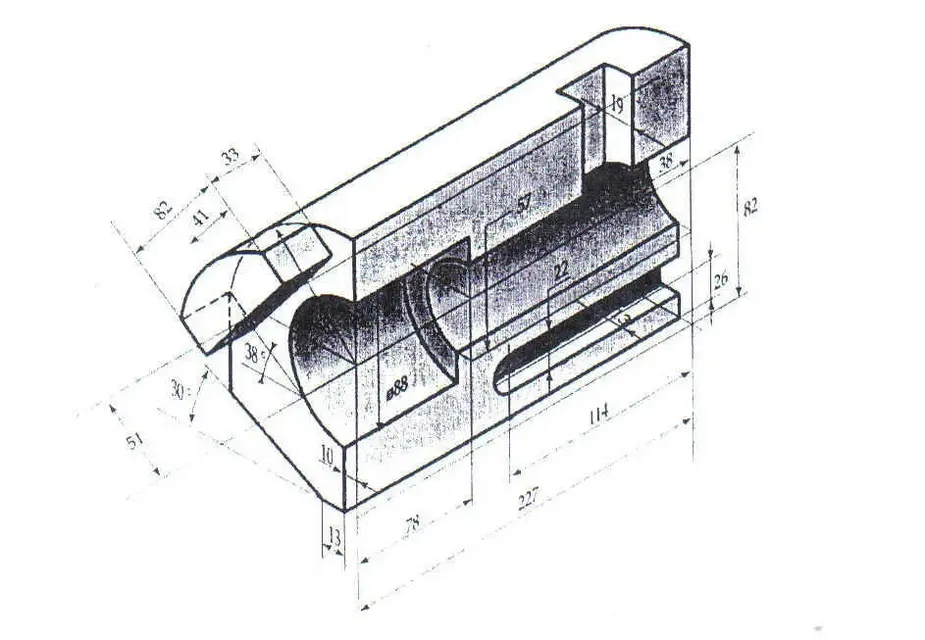
I realized this piece "partial" but I don't know why I have the feeling that is not correct.
sec i sbaglaito some quota surely the problem is to understand which one! !

and then a question "slim" but... Where is that red section there a space between the edge between the 38 and the central excavation?

ps: I tried to create the rectangle for the upper excavation, but does not lack a quota to bind it completely? '
Thank you all!
 

Attachments

  • parziale.rar
    parziale.rar
    70.8 KB · Views: 16
  • lastscan01.webp
    lastscan01.webp
    64.9 KB · Views: 26
I realized this piece "partial" but I don't know why I have the feeling that is not correct.
sec i sbaglaito some quota surely the problem is to understand which one! !
you have wrong cut-extrusion sketch1; the 10 mm wide rectangle must be high enough to cut even the face of the inner hole. changes the value of the quota from 44 to 20, or better yet cancel it and binds the internal summit of the rectangle on the central semicircumference of radius 28,5
I tried to create the rectangle for the upper excavation, but does not lack a quota to bind it completely? '
Thank you all!
Yes, the width is missing. Go to the eye
 
Thanks after lunch I try to change. Then there was no quota.
You know, I'm getting my eye around..xd!
 
Good night or maybe it would be better good morning.
I should model the following piece and I would like to know if the quota of 133 is used to create the two arches that constitute the excavation.

I'm almost sure, but... never, especially at this hour!

ps: Someone would show me how a table would come out that respects all the rules.
I do it almost automatically with solidworks but, for example, the holes on the different views I have to build them individually.

night to all!
 

Attachments

  • lastscan.webp
    lastscan.webp
    122.7 KB · Views: 39
Hello volaff
the 133 second mè serves to create the two arches of the excavation, if you would have seen a universal milling machine make similar excavations, you would have immediately realized. a little real construction of the pieces helps so much regardless of the standard rules in the mechanical design.

the views should be created in number to make clear the view of the details of the piece, with the least number of views.

3 views.
from above where the hole d 22 is located
from side where the doro d20 is located
from below where the hole d 40
or
3 views
two views and one section
 
the lines of half-carry and the tazz of centering are inserted through the annotations.
for the design a frontal view of the asola da 24, one in plant in which you see the two semicircular excavations and a perpendicular section to the asola da 24
 
Bye.
I just modeled this piece at solidworks.
How does it look?
for the table I have respected the norms in relation to axes of symmetry and similar?? ? ?

Your opinion would be of immense help!
Thank you all!
 

Attachments

Meanwhile I modeled the previous one but I have the following problem: when I go to relish the holes of the base they are superimposed to the central part as in the central figure.

Did I make a mistake?
I don't believe sincerely but since I'm yawned I wouldn't be surprised.

Good Sunday to all!
 

Attachments

  • Part4.rar
    Part4.rar
    111.5 KB · Views: 3
  • Immagine_2.webp
    Immagine_2.webp
    78 KB · Views: 17
Meanwhile I modeled the previous one but I have the following problem: when I go to relish the holes of the base they are superimposed to the central part as in the central figure.

Did I make a mistake?
I don't believe sincerely but since I'm yawned I wouldn't be surprised.

Good Sunday to all!
If you've encountered a problem it doesn't cost you anything to control the piece, I'm sure that in checking each quota you'll find the error without indicating it to you.
 
In fact I have also done it but I always arrive at the same point that is the one highlighted at the top post:-)
 
do not control the odds you have put into construction, paarti dal processo iinverso.
check the odds with the structure you got. then with the command measure detects the quotas indicated on the two-dimensional and tickles one by one.
read the quotas well... to the eye without solid I think I understand where you wrong
 

Forum statistics

Threads
44,997
Messages
339,767
Members
4
Latest member
ibt

Members online

No members online now.
Back
Top