• This forum is the machine-generated translation of www.cad3d.it/forum1 - the Italian design community. Several terms are not translated correctly.

parameterization in work on support

  • Thread starter Thread starter if2111
  • Start date Start date

if2111

Guest
Hello everyone
provided that I always parameterized the profiles within the sketch, I wanted to try to do it within the work on support.
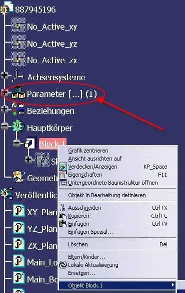
the variables obtained are in brackets and not editable, where did I wrong?
I also noticed that it is not possible to use as reference the h/v terna that turns red as attached image, I also attach the small example file.
thank you all
 

Attachments

It is equivalent to creating a reference system on a 3d entity (e.g. a plan, or better still a surface, even multi pach).
when you activate the object on which you created the work on support all 3d objects you create (rects, spline circumferences ec...) are reacted on the reporting entity.

Hi.
 
It is a good explanation, but as far as parameterization is concerned, can you give me a hand?
Thank you.
 
That's what I think is the method of parameterizing the elements you build on a wos.
If you have special needs, enter an example similar to the problems you are facing.

Hi.
 

Attachments

hi ferrezio
this is definitely a good method to exploit the potential of the wos,
but "parametric" means there are "parameters" to be changed and here they are not.
what I was interested in was to exploit the wos on a plane as it was a sketch and to be able to insert constraints and parameters, for the constraints it seems not to be a problem, but for the parameters come those parameters in brackets that are not editable, as you can see in the example I attached in the first post.
thanks for the collaboration
 
I can't see your percho attachment I don't open the sevenzip and I probably can't even open the file because I use an old cat Realization, but I think you're complicating your life, you just see the parameters of a sketch (see photo1 and photo2).

However in my previous example the parameters are there and are grouped into the indicated tree node (for me this means parameterizing, perhaps you do not see the node and why you have to activate the display in tools\options \infrastruttre\part infrastructure table "view"), however regardless of how they are displayed (eg a 3d straight), the parametes of defiition of the geometry are accessibilbindo the shaft node.

However, if you want to operate as you clearly ask you to change the approach to the model as you can see on the last image by managing the points in an isolated way, you can by means of the 3d constraints you can assign associations of geometric and dimensional type, but the straight is kept under control from the coordinates of the points, but you can not have control over the length, unlike my first method.

Hi.
 

Attachments

  • FOTO1.webp
    FOTO1.webp
    59.6 KB · Views: 22
  • FOTO2.webp
    FOTO2.webp
    44.6 KB · Views: 20
  • FOTO.webp
    FOTO.webp
    77.2 KB · Views: 22
hi ferrezio

Your parameterization is within a sketch, but I, to do a little "academy" I want to complicate things, and the sketch, I don't want to use it.
I'll try again, and I hope I'm ready to put the solution.

Thanks again
 
However, if you want to operate as you clearly ask you to change the approach to the model as you can see on the last image by managing the points in an isolated way, you can by means of the 3d constraints you can assign associations of geometric and dimensional type, but the straight is kept under control from the coordinates of the points, but you can not have control over the length, unlike my first method.
This is what you are looking for, but it is not functional, in the annex you find an example on a floor.

Hi.
 

Attachments

Hello, guys.
Sorry, but I didn't understand the problem.

If it were to have the visible "quotes" comfortably, just place on the feature and with the dx button choose to view them.

validating in the second window that appears, they will remain permanently visible.

there is no need to open the sketcher to editate it
 

Attachments

  • parameter.webp
    parameter.webp
    65.4 KB · Views: 16
the probelematic (if I have understood) is the attempt of if you can trace a planar geometric entity manageable with graphics entities as in the sketch environment, then exploiting the possibility to insert the 3d constraints, but this is in conflict with the parameters of the 3d geometries in turn are constraints.

in practice tries to operate directly as today you work using 3dshape ds.
so the problem is only operational.

Hi.
 
hello falonef, I noticed that near parameter you have the symbol [...] (1) .
What does that mean?
Hi:
 

Attachments

  • parameter2.webp
    parameter2.webp
    41.7 KB · Views: 14
this stef the symbol [...] (1) in the logical tree is to indicate that parameters are present but hidden.

In this case 1 is telling us that only one parameter is hidden.

In our case we have hidden a parameter that controls whether the same catpart document was created from a template so the user works correctly.

if the document was created by new -> file the logical tree would not contain this (for us) valuable information.

ps: the users, however, do not need to know this.
I have to load the basic model (protected) and save it under another name so it has practically a copy with all set rules already set but......

keeps the same uuid!! !
 
In our case we have hidden a parameter that controls whether the same catpart document was created from a template so the user works correctly.

if the document was created by new -> file the logical tree would not contain this (for us) valuable information.

keeps the same uuid!! !
Interesting! ! !
How did you create this procedure...
Thank you:
 
I'm sorry, I don't want to destroy the current debate, but yes. we created an application that virtually automatically copies the document from a server on the user machine and renames the file.
attention: the used command is new > save as ... so we keep the basic model settings (color the blue thread, parameters etc.)
 
It is equivalent to creating a reference system on a 3d entity (e.g. a plan, or better still a surface, even multi pach).
when you activate the object on which you created the work on support all 3d objects you create (rects, spline circumferences ec...) are reacted on the reporting entity.

Hi.
therefore it is a virtual plan outside the sketcher that allows you to construct but not in space (without the 3rd dimension).

Right? ? ?
 
simplified yes, but if you are in technical superfic and how to work in the third dimension.
Also when you make the subject's table if as a fencing plan you choose the object related to the work on support, you will appear the lattice of the coordinates on the table.
This particular behaviour of wire-frame geometries applies even when within a wf command (e.g. line) in the support field indicate for example a plane or a surface (e.g. an angled straight on a cylindrical surface).

Hi.
 

Forum statistics

Threads
44,997
Messages
339,767
Members
4
Latest member
ibt

Members online

No members online now.
Back
Top