frade24
Guest
Hello everyone, my name is Franciscan and I am a graduate in mechanical engineering. I'm new in the forum and I write because I can't solve a problem and on the net I found nothing that could help me or at least I can't apply it to my needs. I apologize in advance if my question is banal but I am not very knowledgeable about software and I have exclusively university teaching knowledge.
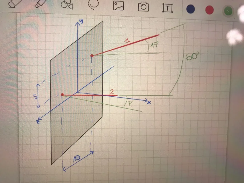
for my thesis project, I need to create two lines in space that are parametrizable. they indicate a direction of drilling (image allego). I need to parameterize the inclination in space and their reciprocal position (they are independent of each other). I tried to make reference plans on which to create these lines so as to "check" the inclination of the plans and therefore of the lines, but I can "check" only 2 parameters. I did it by inserting an excel data table. I don't know if this is the right way or not. I also tried to import coordinates through a "txt" file corresponding to the extreme points of the lines, thus obtaining in solidworks a cloud of points, but I do not know how to parameterize the same.
I hope you can help me, thank you in advance.