• This forum is the machine-generated translation of www.cad3d.it/forum1 - the Italian design community. Several terms are not translated correctly.

"personalized" roof drain

  • Thread starter Thread starter ChIP_83
  • Start date Start date

ChIP_83

Guest
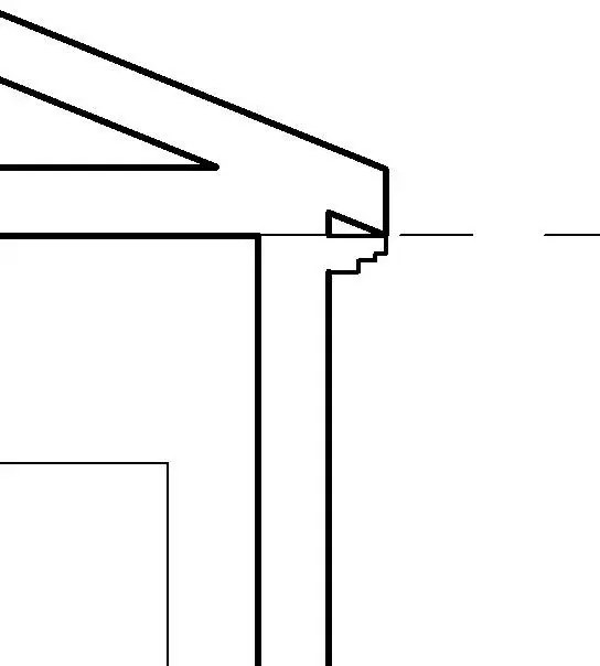
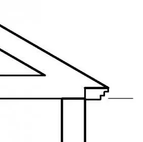
I saw that after creating a roof, selecting it, from the properties allows me to choose the type of "crown" that he calls "cut beams", but the choices are limiting (are 3 types).

How do I do to make a frame of the personalized gravy?
I like to be able to draw a profile of the frame and then see it applied along the same.
 
What do you mean?
- a frame in the head of the river (near/under the canal)
- a frame on the undergrove that collects the eaves with the wall
 
You could use a route extrusion as a local model opp if you think you often use a family based on line.. .
 
In my opinion the + simple thing is to create a family profile and upload it to the project.
 
as you told me it is possible to make the gronda, but from the practical point of view it is not that it is a great deal.
first of all because the element is seen as a "any element" a set of polygons to which no property is attributed, as instead happens in the case of the roof.
Therefore, in the case of complex roofs, I have to place the elements on each frame and change them in case change the trend of the roof. I have to match the corners, etc.

there is no way to associate this extrusion of the profile to the perimeter of the roof... how? :
 
as suggested fcrprogetti. ... loading a profile to use as a gronday.... .
create the profile and in parameters and categories of families the checks the use grondaia. .
load it in the project and with the command grondaia the necks on the profile of the roof...
 
as suggested fcrprogetti. ... loading a profile to use as a gronday.... .
create the profile and in parameters and categories of families the checks the use grondaia. .
load it in the project and with the command grondaia the necks on the profile of the roof...
Wait a minute, excuse my ignorance, but could you explain it by step?
I don't know if I have to create a family or do it directly. . .
 
1-open a new profile family.
2-in parameters and categories of families imposed in the properties use gronday. in this way from the properties of the grondaia object within the project you can select it as profile to extrude for the creation of the same
3-draw the profile bearing in mind that the axle cross is the insertion point (origin) of the profile that you can invert rotate etc according to need. . .
4-Locate the profile in the project with the appropriate button
5-positions a gronday on the perimeter of the roof with the appropriate command.tetto>grondaia.
6-the selection and duplichi.
7-In the profile type properties choose the profile you created.

I hope I haven't forgotten anything...
Hi.
Thanks, doing as you told me I almost managed to solve it.
I still have a problem:

- if I keep the gronda "low" compared to the lines of the work plan of the editor families you come to create the space you see in the image that I do not know how to "fill". If you raise them, the gronda is "enlobed" inside the roof with the result that you obviously do not see.

- if you want to make "the first part of the sling" (the highest) of reduced thickness, I should by force decrease the thickness of the sloping ceiling of the roof, since the first "grade" is constituted precisely from the roof.
but if I do this, the change will also affect the other bonfires or points I would not like to change.

How can I do that?
 

Attachments

  • catturanx.webp
    catturanx.webp
    5.3 KB · Views: 21
Last edited by a moderator:
I don't know if one thing is acceptable, I only deal with insides:tongue: if you have set double squared cut in the roof beam cut parameter....
 

Attachments

  • Immagine.webp
    Immagine.webp
    2.4 KB · Views: 17
... or the design of the profile must contain the inclined upper side, which matches the undergrove ....
 
I don't know if one thing is acceptable, I only deal with insides:tongue: if you have set double squared cut in the roof beam cut parameter....
Thank you, so I solved.
I thought about it, too, but when I tried to do it, I was mistaken in the creation of the sling and didn't change the parameter.
Now I saw that it was enough to clear the gronda, change the parameter and remake it; works perfectly :d
 
I add another request. . .
...and if you want to do, instead of the classic frame, a 5 cm granite slab. supported by small granite shelves (15x20 cm) framed in the cord and interspersed by about 60 cm ?

In other words, to make the slab, I realized that it pastes an extrusion profile, but to repeat an element several times along the perimeter of the roof (at a prefixed distance), how do I do?
 
mmh even if it is not exactly a bim solution.. you can draw the granite shelf in a family for balustrades and follow the profile of your gronda with the railing tool. or create a family of beams with the shape of your shelf and define a system of beams under the sling, a little more bim..

Hi.
 
I would do this::rolleyes:

1) plate with the usual method (as indicated by tristan)
2) generic model family based on line.
nests inside a shelf family (even here generic model, popping up based on work plan in parameters and categories of families).
after what you make a matrix using the method move to inserting the distance that best suits you.
selections at the end of the quota indicating the number of objects belonging to the matrix and the parameters so that you can decide the number of shelves to be inserted on each side.

if before charging it in a project you set a different category you can also count the number in abaco.:finger:

ps:to place it correctly you can use geometry present in the project or draw lines that you can then hide.....magari preparing an ad hoc type...:wink:
 

Attachments

  • Senza titolo-2.webp
    Senza titolo-2.webp
    45.1 KB · Views: 13
  • Senza titolo-4.webp
    Senza titolo-4.webp
    49.6 KB · Views: 9

Forum statistics

Threads
44,997
Messages
339,767
Members
4
Latest member
ibt

Members online

No members online now.
Back
Top