• This forum is the machine-generated translation of www.cad3d.it/forum1 - the Italian design community. Several terms are not translated correctly.

pin sizing

  • Thread starter Thread starter Merka73
  • Start date Start date
Meanwhile I attach the diagrams related to the support.
I hypothesized the internal constraint pin+ghiere as a bond that prevents x, y, z and rotations from y, z axes.
fx, fy, rcx, rcy values derive from the free body diagram for the whole system.
Do you agree with the setting?
the rest the place tomorrow (the eyelids see me hour)

Thank you.
I agree. You've come to the static solution now. then admissible pressure and refractive sheet.
then do that dynamic and finish everything do two fems (static and dynamic) putting forces on the right areas and verify how much calculated. compare, report and present.

then if you want to parameterize everything according to the angle and you will have the values in all positions.
 
the spacer in red is made of teflon (or other antifriction material) and has dint=46; dest=100; thickness=5mm.
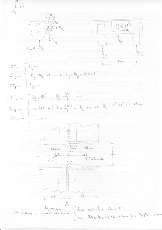
then I apologize, the resulting moment can be considered all at the expense of the pin.
from a quick and simple calculation to me it turns out that on the pin acts a moment of 9900 nm.
 
here are the wheels support diagrams.
I get a result similar to that of paolo.
for static sizing the usual equations apply (see attachment of mechanicsmg).
for the dynamic one: have we not already done it considering an additional load of 1000kg for any holes??? otherwise how would it be done?
I don't remember the fatigue dimensioning anymore:frown:

What is the breaking and yielding load of 38nicrmo4?
do you know the corresponding European designation?

Palo
I am not clear about the material of the washer. how does the mattress affect the loads of the pin?

Mechanical
You can tell me the section of the Eurocodes about the size of the pins you told me.

bye
 

Attachments

  • FBD gruppo motoruote.webp
    FBD gruppo motoruote.webp
    238.1 KB · Views: 41
designation and mechanical characteristics quirupture and yielding load depends on surface hardness and remediation treatment.

in the sizing you have added a force but you have not made dynamics to fatigue that is necessary.

the pins are treated in eurocode 3 also said uni en 1993-1-8:2005

calculation process ok.

fatigue testing (non-sizing) qui with method of goug pollard. otherwise you need to determine the real wohler curve of the pin and see how many cycles it breaks.

the material must be antifriction (a cartilage for iron pieces), then or nylon, bronze, brass. substantially must consumers and absorb the forces that are generated in mating games.
 
for the dynamic one: have we not already done it considering an additional load of 1000kg for any holes??? otherwise how would it be done?
Taking 10000n additional pulse for the holes is arbitrary, depends on the time when the fall is shocked, it could be much less but also much more.

I don't remember the fatigue dimensioning anymore:frown:
fatigue dimensionalization, which then as mg writes is actually a verification, requires a complex study especially in this case where pulses are occasional and stochastic and not regular cycles. However, it is a statistical and non-determining approach. given the extreme difficulty of the case I would concentrate on the less expensive work of identifying the peak values, therefore dynamic sizing, so as to remove the stress conditions of the fatigued material.

Palo
I am not clear about the material of the washer. how does the mattress affect the loads of the pin?
I consider teflon and polymers in general very yielding respect to a alloy steel, so I consider negligible the action of such a small washer against the action of the pin. different if you consider a washer or rhin in bronze, able to absorb part of the moment.
 
As I think it is unlikely that you can have the wohler curve of the pin, you may try to follow the indications of norms (e.g. 7670) that allow to trace back to the permissible tension to fatigue starting from the breaking load of the material.
for example, for symmetric alternation voltage:
(c)
in which the coeff. to the denominator are referred to the carving, surface state, size, corrosion.
for cycles with average voltage different from zero the value so found can be adjusted analytically.
Good job
 
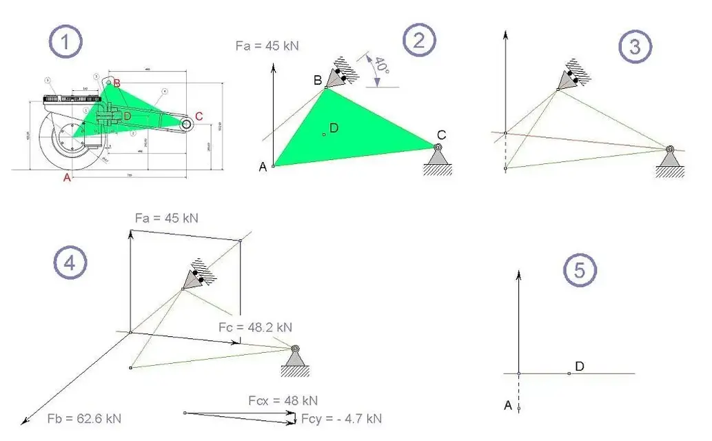
I've done it a few minutes and I've made it there, and as promised, I have a graphic calculation solution.

comment the diagrams referring to their numbering:

1) for simplicity I assumed that the object behaves as a rigid body, including pin, and I stylized it with a triangle (green).

2) I apply the force in a (mode), in b I have a cart so that I have only one reaction according to the specified direction, in c I apply a zipper that can react in any direction.

3) I apply the carrier to the intersection point between its action line and the reaction line of the cart b. from that point I have traced the conjunct to c, and this will be the right of action of the reaction of the bond c.

4) balance! with the simple rule of the parallelogram I got fb and fc. I think it is understood well from the figure and I do not dilute myself beyond. for completeness I have decomposed fc in its x,y components.

5) the moment when compared to the pole d is obtained by applying the carrier does in the intersection point between its act of action and the passing perpendicular to the point d.

a greeting
 

Attachments

  • Diagrammi.webp
    Diagrammi.webp
    35.2 KB · Views: 37
I've done it a few minutes and I've made it there, and as promised, I have a graphic calculation solution.

comment the diagrams referring to their numbering:

1) for simplicity I assumed that the object behaves as a rigid body, including pin, and I stylized it with a triangle (green).

2) I apply the force in a (mode), in b I have a cart so that I have only one reaction according to the specified direction, in c I apply a zipper that can react in any direction.

3) I apply the carrier to the intersection point between its action line and the reaction line of the cart b. from that point I have traced the conjunct to c, and this will be the right of action of the reaction of the bond c.

4) balance! with the simple rule of the parallelogram I got fb and fc. I think it is understood well from the figure and I do not dilute myself beyond. for completeness I have decomposed fc in its x,y components.

5) the moment when compared to the pole d is obtained by applying the carrier does in the intersection point between its act of action and the passing perpendicular to the point d.

a greeting
Hem... What's the matter? even if it was rigid body, as in my first approximation it would be like from my first image, horizontal beam with zipper and cart with force applied....without needing to shake the graphic solution.

if you unpack everything as analyzed previously you get the result on the body under examination.
 
As I think it is unlikely that you can have the wohler curve of the pin, you may try to follow the indications of norms (e.g. 7670) that allow to trace back to the permissible tension to fatigue starting from the breaking load of the material.
for example, for symmetric alternation voltage:
(c)
in which the coeff. to the denominator are referred to the carving, surface state, size, corrosion.
for cycles with average voltage different from zero the value so found can be adjusted analytically.
Good job
if you follow the astm standards you can build the wohler diagram and evaluate the real case with all coefficients, load type (traction/flexor/torsion), dimensional, surface finish, temperature, reliability, treatments and coatings.

see my post qui.
 
this thread has become really interesting.
thanks for the collaboration and links.

paolo solves it by graphic (I would never have come to mind) and the results converge.
I had a good time retracing some science of construction.

Thanks again
 
could you have a dispensation for graphic solutions explained well? I must be honest, always that analytical I used and that graphics never explained.
 
compliments for this interesting discussion,
I'm intruding to ask for something about spaceship: in case it had been, for example, steel instead of teflon as you would have subdivided the amount of time to load the spacer and to load the pin?
 
could you have a dispensation for graphic solutions explained well? I must be honest, always that analytical I used and that graphics never explained.
Yes, unfortunately the graphic approach I have never seen him deal systematically, as for other things it is about making a summary of information scattered and dispersed between different books and dispenses. I showed this because in another discussion, merka73 asked me what I had used to produce those diagrams.

compliments for this interesting discussion,
I'm intruding to ask for something about spaceship: in case it had been, for example, steel instead of teflon as you would have subdivided the amount of time to load the spacer and to load the pin?
to say it is necessary to solve the entire system subjected to the fact that in this case it would no longer consist of the only two sleeves that contain the pin but also from the base (distantial) between the sleeves; and you have to put yourself there because we have nothing to do with simple point reactions, so the base has a circular geometry.
 
Good morning to all,

I am a new community attendant and I will be grateful to anyone who helps me out of this impasse:
is verifying to wear a hardened steel pin on which flows a bushing also in tempered steel (pin 18nicrmo5 cem+tmp+rinv , bushing 38nicrmo4 tmp+rinv roughness 0.4/0.8, lubrication:fat):
I cannot find the coefficient k (pm.v) to be compared to the maximum pressure I obtain for my pin (n=70 g/1' sense of alternating rotation) because the values shown on many tables refer to materials for the realization of friction elements such as sintered, bronze or metal without specification.

Does anyone have a table with the values of alternative materials to the classic ones where I can find my value? ? ?

link of the pdf used for verification (page 27)
Thank you.
http://www.unife.it/ing/meccanica/insegnamenti/elementi_costruttivi_trasmissioni_potenza/dispense-per-il-corso/formulario_2009_1.pdf
 

Forum statistics

Threads
44,997
Messages
339,767
Members
4
Latest member
ibt

Members online

No members online now.
Back
Top