doc83
Guest
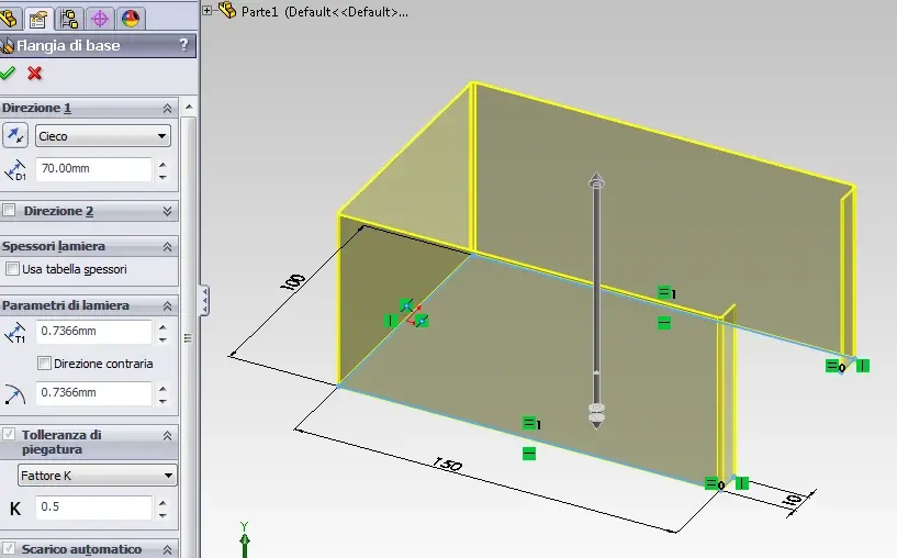
hello to all boys!! I'm designing an electronic device, and I must have the front (the one on the right) swiped from the rest of the furniture.
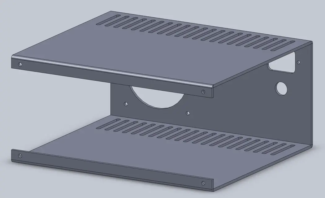
I explain: in the profile view, which I attach, it is seen that the bending carried out by the above program leaves a game in the lower edge. I want the two curves of sheet metal instead and leave me 1cm on each side (because then the panel will be fixed in another way).... how can I do? the sheet function does not allow me (justly) to have two cuts, because otherwise what is the front panel (right) would come to "flot in the void". instead I want to remove it from the middle, because then it will be done by another part (it will be done in plexi and not in 3mm aluminum). in practice instead of the right side, I would like the two rounded edges and two 10mm long flanges.... is it possible according to you with this procedure? thank you all and apologize for the question maybe stupid, but they are at first with solidworks!
I explain: in the profile view, which I attach, it is seen that the bending carried out by the above program leaves a game in the lower edge. I want the two curves of sheet metal instead and leave me 1cm on each side (because then the panel will be fixed in another way).... how can I do? the sheet function does not allow me (justly) to have two cuts, because otherwise what is the front panel (right) would come to "flot in the void". instead I want to remove it from the middle, because then it will be done by another part (it will be done in plexi and not in 3mm aluminum). in practice instead of the right side, I would like the two rounded edges and two 10mm long flanges.... is it possible according to you with this procedure? thank you all and apologize for the question maybe stupid, but they are at first with solidworks!