• This forum is the machine-generated translation of www.cad3d.it/forum1 - the Italian design community. Several terms are not translated correctly.

problem nervature

  • Thread starter Thread starter rafing2
  • Start date Start date

rafing2

Guest
Good morning.
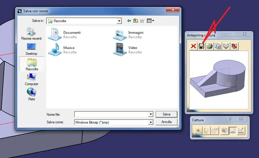
I need a help I need to draw a bracket with a rib in the median plane that starts from the cylinder and reaches the extreme of the parallelepiped as you can see from the attached image but if I try to make the rib exploiting the sketch reported gives me the invalid profile body error you would know to indicate the right way of execution.
greetings
 

Attachments

  • Nervatura.webp
    Nervatura.webp
    13.5 KB · Views: 55
to make that kind of ribs on the vertical bench you have to close the sketch as in the photo.
otherwise you have to change plan and apply prism condition to thickness, as in photo 2

Hi.
 

Attachments

  • Nervatura2.webp
    Nervatura2.webp
    15.5 KB · Views: 65
  • Nervatura1.webp
    Nervatura1.webp
    15.9 KB · Views: 58
Thank you for the answer.
As for the first solution I have another question to ask you, doing in this way we say you create extra material within the solid that even if it has not seen is present cmq I was wondering if it is strict as what.
Say hi.
 
modelers born in the last 15 years are called feature based, because the model you create is generated by creating a sequence of basic primitives (prisms or pockets) that generate a unique volume.
This means that every time you create in a model two features (in the specific caia contained both in the partbody container) the system in addition to the volume creation operation also creates a sum operation (boolean algebra) between the two volumes, it would be a subtraction if it were a pocket (it happens the same thing even if the two volumes do not connect).

in your case even if the starting sketch covers the model, the final solution remains a unique volume.

Hi.
 
There are two systems to make this kind of ribs.
1st- run the closed sketch and let it enter the round part as long as it is enough so that the thickness remains inside.
2nd- this solution is the canonical one of catia and that is to make a rib uses the icon "nervatura" and this is the procedure : do the sketch open on the side of the round surface then go on the icon "nervatura" turn on "on the side " put the thickness , "fibra neutra accesa" select the sketch he will give you an error of definition of the feature click on ok and
seems long but when you know the procedure is simple and is the best system for any changes in the sketch and thickness.
Greetings
 
I'm sorry if I need information for you simple.
I would like to send an image created by catia v5 that puts it in my folder "images"
when I want to put it in a message and click insert image asks me url of the image i.e. an internet address.
Can you tell me how to do this?
Thank you.
 
Dorian, but the sketch on which plane should be done, if I do it as in figure I can make maximum rib of 1 mm.
thanks to all for the info.
 
I don't understand why only 1 mm
look at pictures
Hi.
 

Attachments

  • nerv3.webp
    nerv3.webp
    30.4 KB · Views: 33
  • nerv4.webp
    nerv4.webp
    33.2 KB · Views: 24
I had not understood in fact you are right not does it, I try some other solution
and if I can make you know
Hi.
 
per doriano
I'm sorry if I need information for you simple.
I would like to send an image created by catia v5 that puts it in my folder "images"
when I want to put it in a message and click insert image asks me url of the image i.e. an internet address.
Can you tell me how to do this?
Thank you.
I can't locate your problem because if I save the hole through the preview panel, I can access my disk.

for rafing2

If your purpose is to avoid the effect of photo 2 I can assure you that it is completely negligible when working, you will notice it as soon as you add fittings.
if your purpose is didactic in the third photo see the solution with cutting a multi section surface and three guide curves.
the cut must be carried out within a suitably combined body with boolean assembled in the modeling of the support.

Hello everyone
 

Attachments

  • memorizzazione di  foto.webp
    memorizzazione di foto.webp
    34 KB · Views: 22
  • sezione.webp
    sezione.webp
    30.9 KB · Views: 23
  • costola.webp
    costola.webp
    96.9 KB · Views: 28
thanks Ferrantio I solved the problem having never attached photos to the messages I did not know that I had to go on "adhesive management".
for the problem of ribs I subscribe to what to the said, can add (always if the purpose is didactic) that there are other solutions using the surfaces, or changing from birth to surfaces.
look also this solution is simple and not suitable for cuts or material subtraction.
Greetings
 

Attachments

  • nerva4.webp
    nerva4.webp
    26.6 KB · Views: 26
thanks Ferrantio I solved the problem having never attached photos to the messages I did not know that I had to go on "adhesive management".
for the problem of ribs I subscribe to what to the said, can add (always if the purpose is didactic) that there are other solutions using the surfaces, or changing from birth to surfaces.
look also this solution is simple and not suitable for cuts or material subtraction.
Greetings
But how did you do that?

I have this design and found it as a quicker solution only this:
Immagine2.webp
Immagine 3.webp
Immagine 4.webpgreetings
 
from the image is not clear, but from what I see, and what he says, I can imagine that he built the rib in the following way:
the main thing has as a basic settling the hybrid modeling of catia, i.e. solid models and surfaces in the partbody;
later in the gsd area (seneravi shape dsingn or wire fram shape design of mechanics) built a wire frame (lines, white) on which he built a series of pach that then joined.
in pardesign used the function that you find in the group of "surface-based solids" sewing of surface.

a second method could be that of extracting the faces and limiting and various surfaces, but it looks a lot like the previous one changes only the departure.

Hi.
hi ferrrezio .in fact manages the thing, but there are too long steps, and I need the fastest method and without anything to remove to doriano I think it is mine.

Greetings
 

Forum statistics

Threads
44,997
Messages
339,767
Members
4
Latest member
ibt

Members online

No members online now.
Back
Top