xLOGANx
Guest
Good afternoon to all! ! !
I write to ask you for help, a hand, to solve a problem. Forgive the image very rough, but I had little time to prepare it. :tongue:
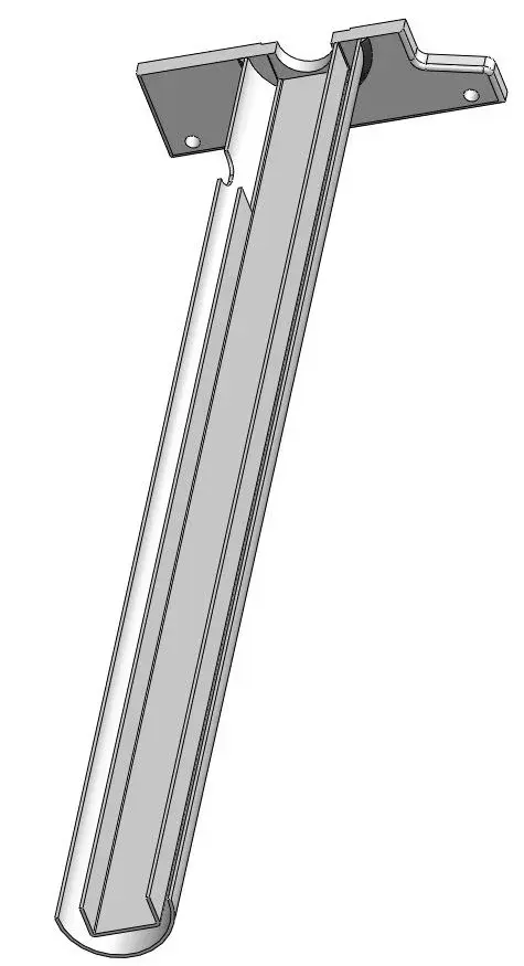
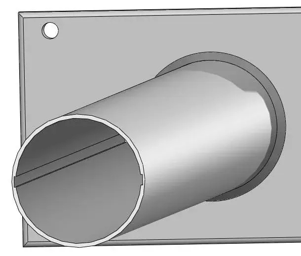
in the figure is represented a lifting group of a plan (in section obviously). the fixed plate, at the bottom, has a circular pocket inside which is inserted this tube called inner column. There is then a welding cord that keeps everything. the plate is then connected to a mobile frame that is represented here.
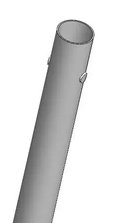
inside this column, there is an oleodynamic piston that will help to lift the floor I told you. the external column, that is the second tube, flows on the inner column due to the effect of the piston: The bushings, visible in the photo, are used to ensure linear operation. the piston rod acts on the push cylinder (a cylinder obtained from the full for turning), allowing the lifting of the structure above.
In principle, this is the description of the system sto. the problem that I put to you concerns the relative rotation of the outer tube compared to the inner tube, which must not be absolutely there. the only movement to be ensured is the simple translation of the outer tube compared to the internal one.
would you have to recommend me some solutions?? I would have found one, but it seems too turkey (if you want I also place the image of my solution). I'm convinced there's something easier... but I can't see it.
also because, everything must be inexpensive and removable; My solution, on the other hand, makes the replacement of the piston uneasy.
thank you all, girl!!! !
I write to ask you for help, a hand, to solve a problem. Forgive the image very rough, but I had little time to prepare it. :tongue:
in the figure is represented a lifting group of a plan (in section obviously). the fixed plate, at the bottom, has a circular pocket inside which is inserted this tube called inner column. There is then a welding cord that keeps everything. the plate is then connected to a mobile frame that is represented here.
inside this column, there is an oleodynamic piston that will help to lift the floor I told you. the external column, that is the second tube, flows on the inner column due to the effect of the piston: The bushings, visible in the photo, are used to ensure linear operation. the piston rod acts on the push cylinder (a cylinder obtained from the full for turning), allowing the lifting of the structure above.
In principle, this is the description of the system sto. the problem that I put to you concerns the relative rotation of the outer tube compared to the inner tube, which must not be absolutely there. the only movement to be ensured is the simple translation of the outer tube compared to the internal one.
would you have to recommend me some solutions?? I would have found one, but it seems too turkey (if you want I also place the image of my solution). I'm convinced there's something easier... but I can't see it.
also because, everything must be inexpensive and removable; My solution, on the other hand, makes the replacement of the piston uneasy.
thank you all, girl!!! !


 ). However, I try to see these two mechanisms reported by hunter. I didn't think so. for the problem related to the angle game... yes, actually it is a present problem. Fortunately, the guide does not need precision pushed as, as mentioned at the beginning, the system must lift a plan on which other elements rest. I'll let you know.