Raind
Guest
Good morning, guys, we're three students planning a warehouse lifter.
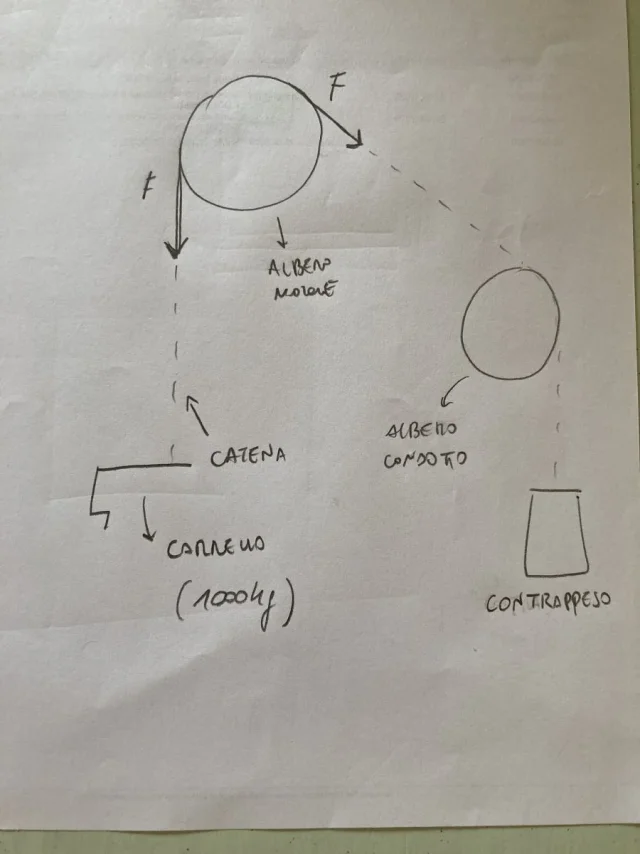
we chose chain and began to consider the forces on the cart (as you can see from technical relationships). the cart is lifted by an electric motor, which is connected to the two motor semi-axis by means of a motor.
we stuck on the sizing of the 2 trees, because, being a static analysis, we did not consider the torque of the engine. someone could give us a tip on how to proceed to the sizing of the tree and how to proceed in the work. Thank you very much to all.
Attachments
-
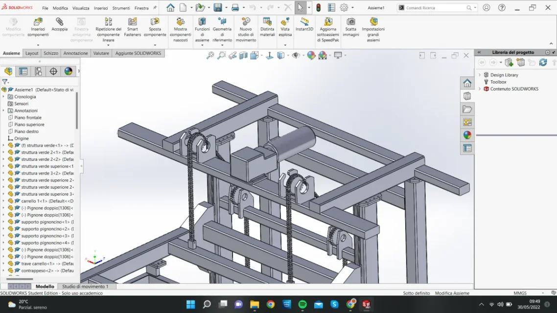 Immagine 2022-05-30 094954.webp98.2 KB · Views: 90
 -
 Immagine 2022-05-30 094906.webp82.8 KB · Views: 81
 -
 Immagine 2022-05-30 095042.webp84.2 KB · Views: 77
 -
Materiali_lifter.pdf1 MB · Views: 29
-
Motore Elettrico (1).pdf59.2 KB · Views: 25
-
Scelta Catena (Prova).pdf1.2 MB · Views: 25
-
Motoriduttore ad assi ortogonali.pdf52.1 KB · Views: 22
-
CDS Carrello.pdf290.2 KB · Views: 21